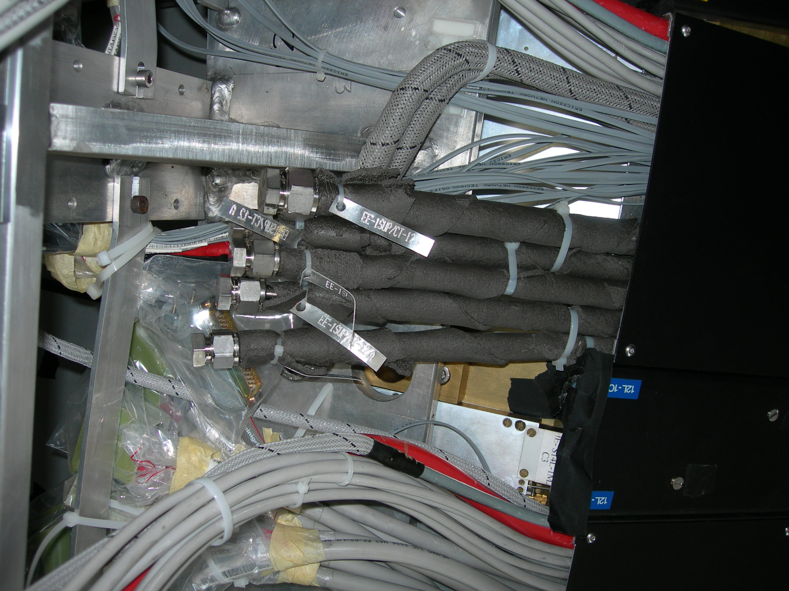
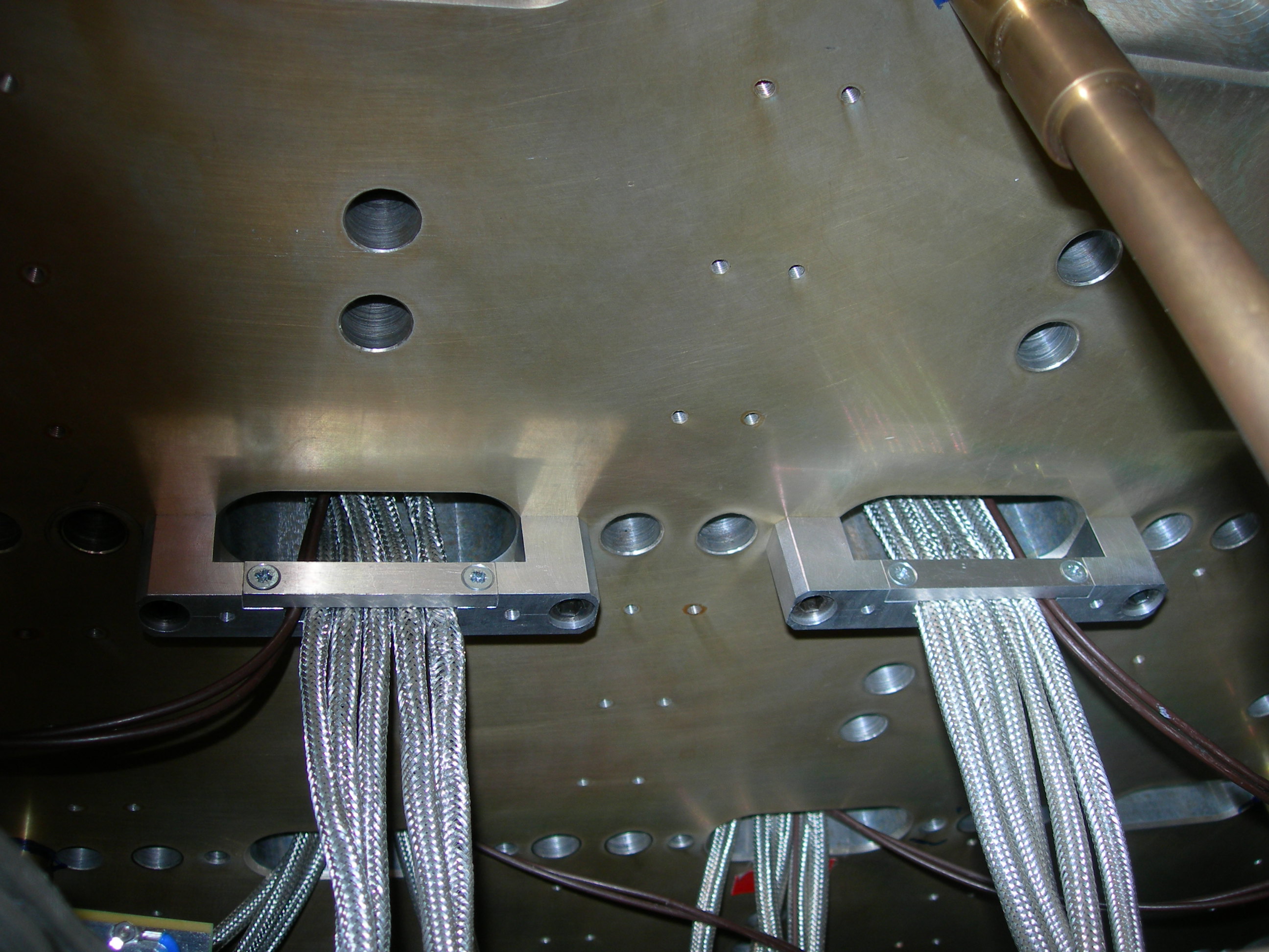
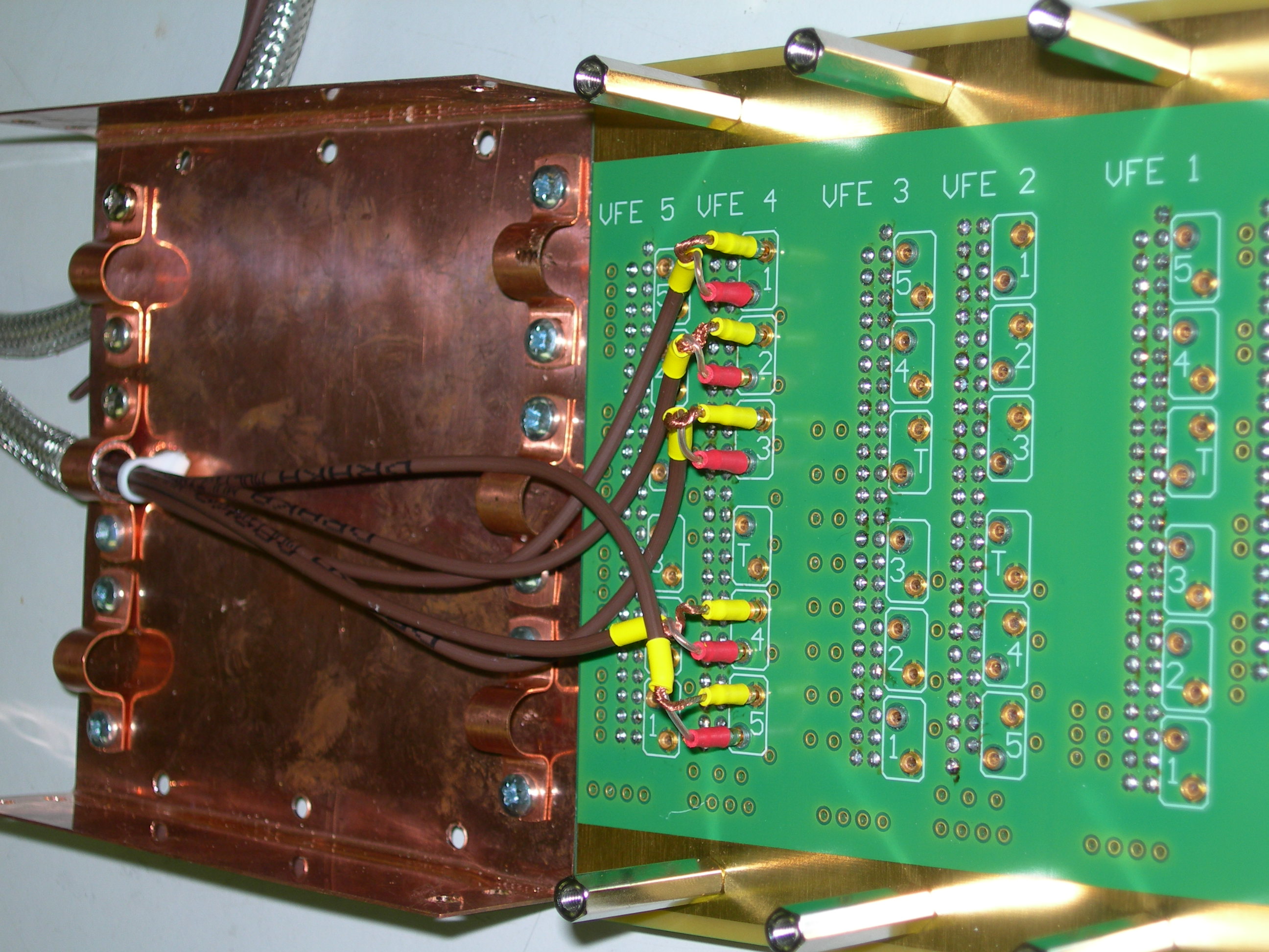
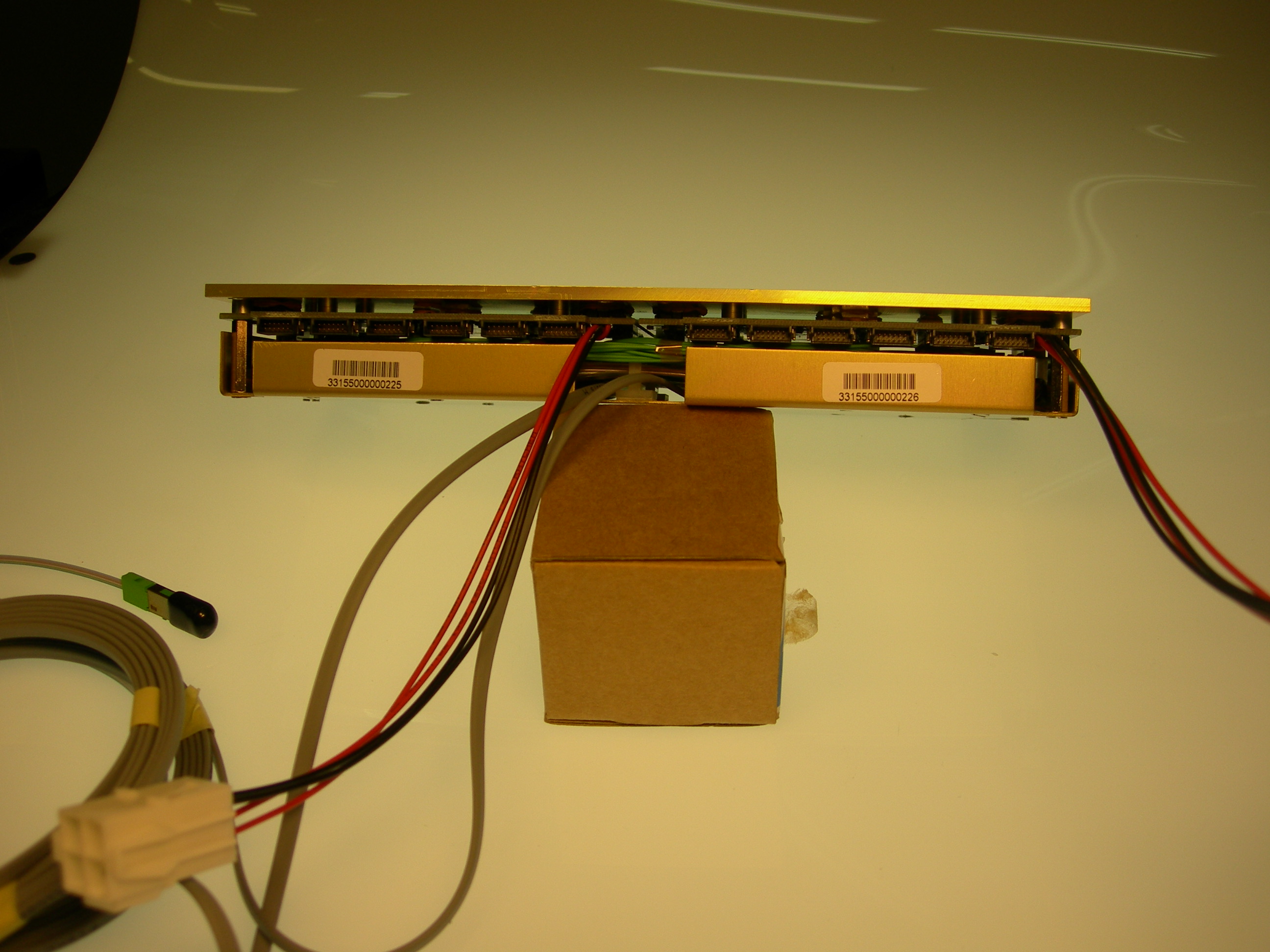
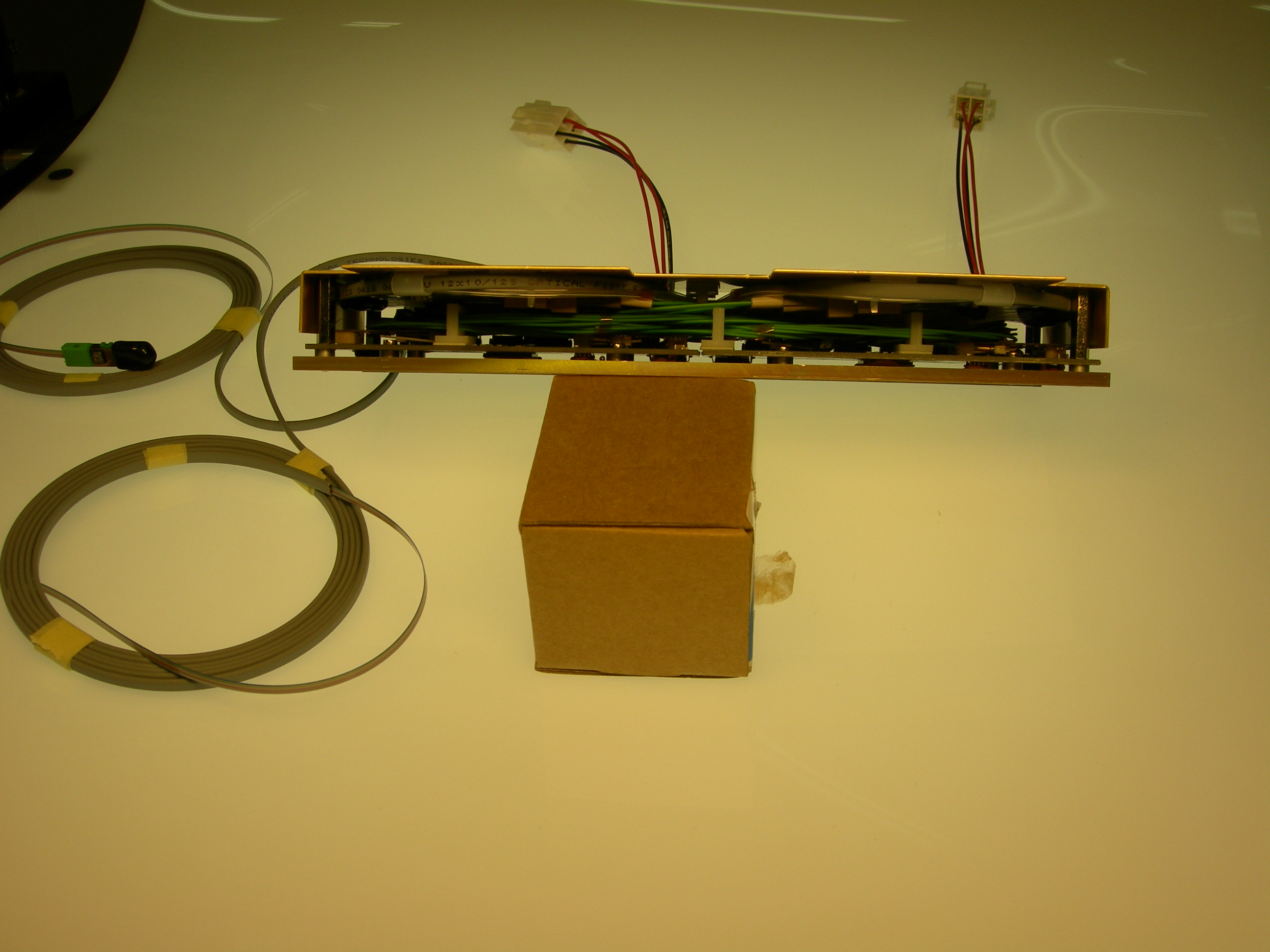
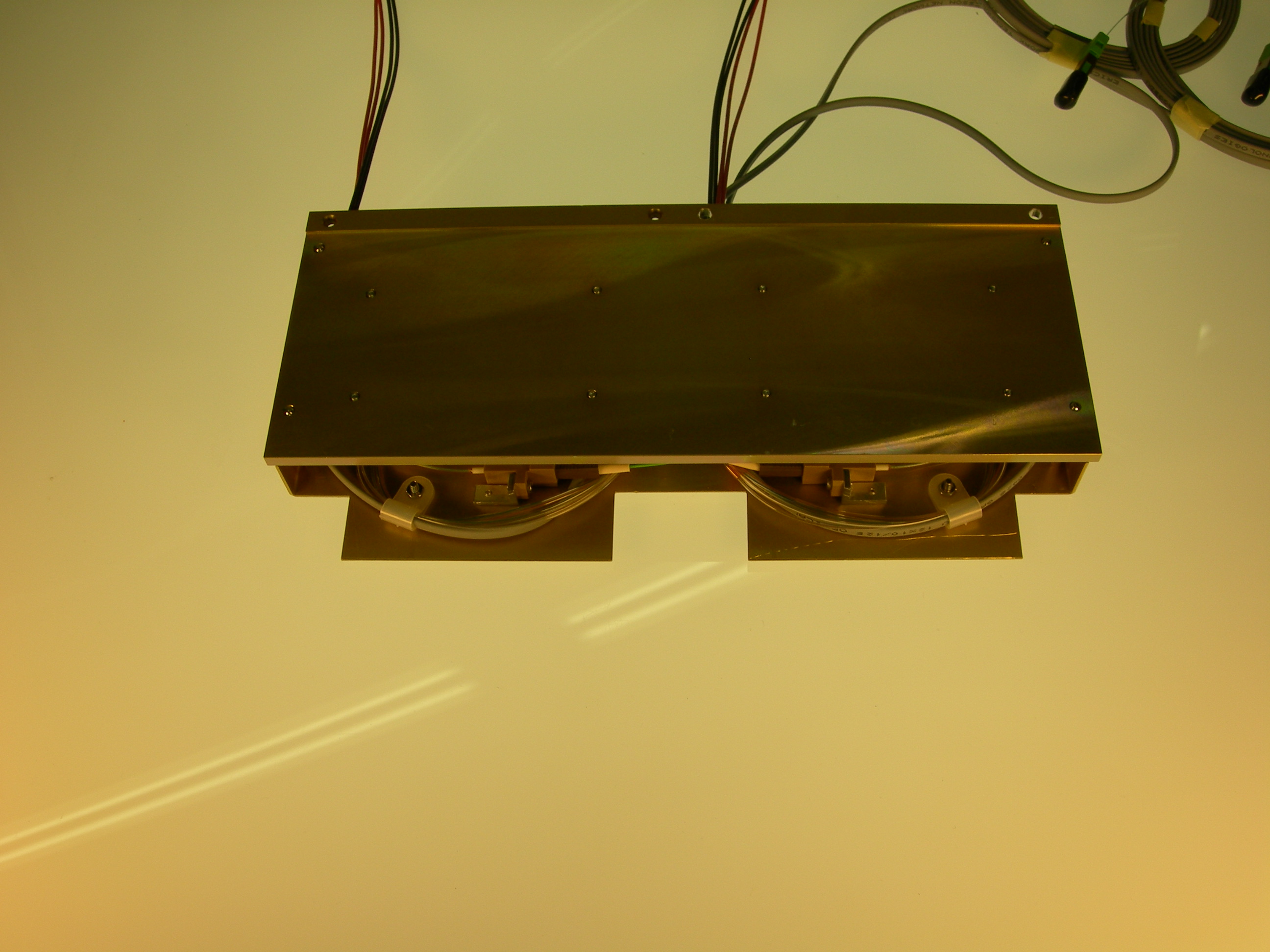
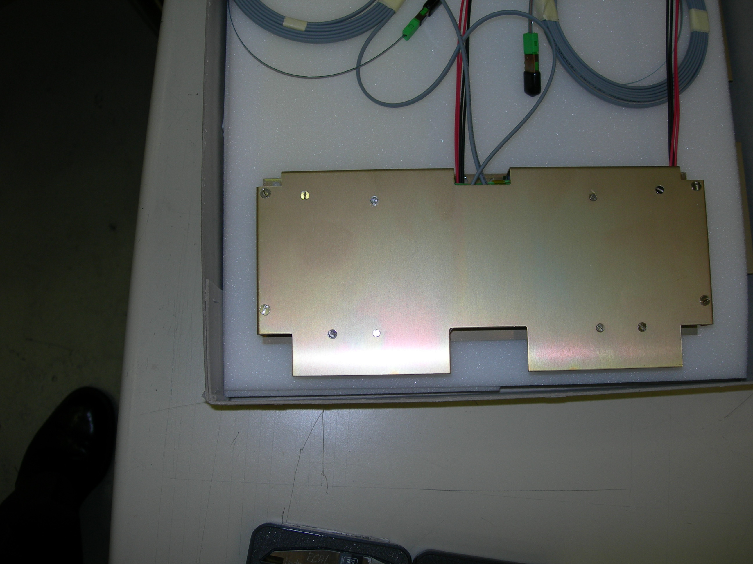
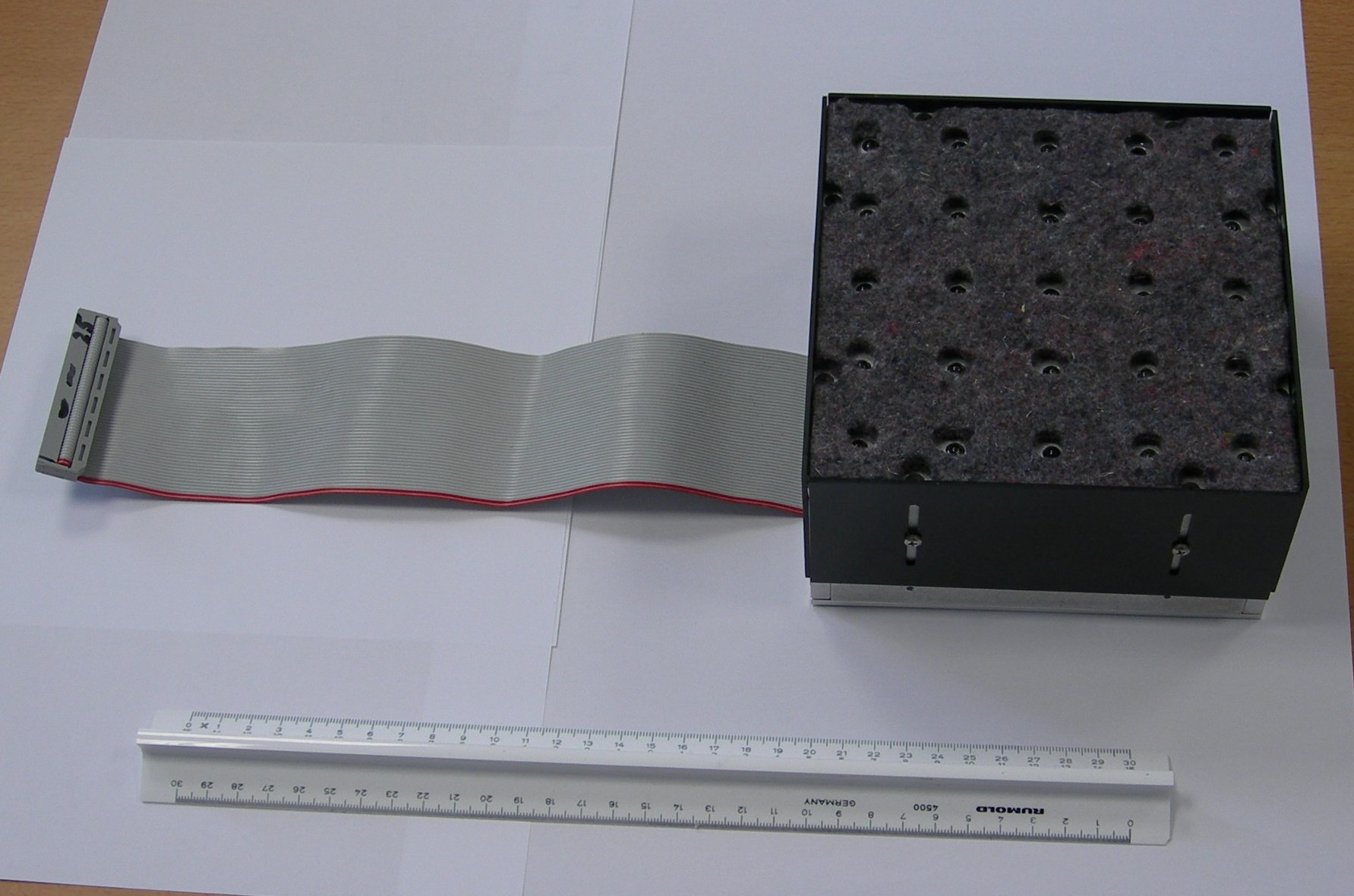
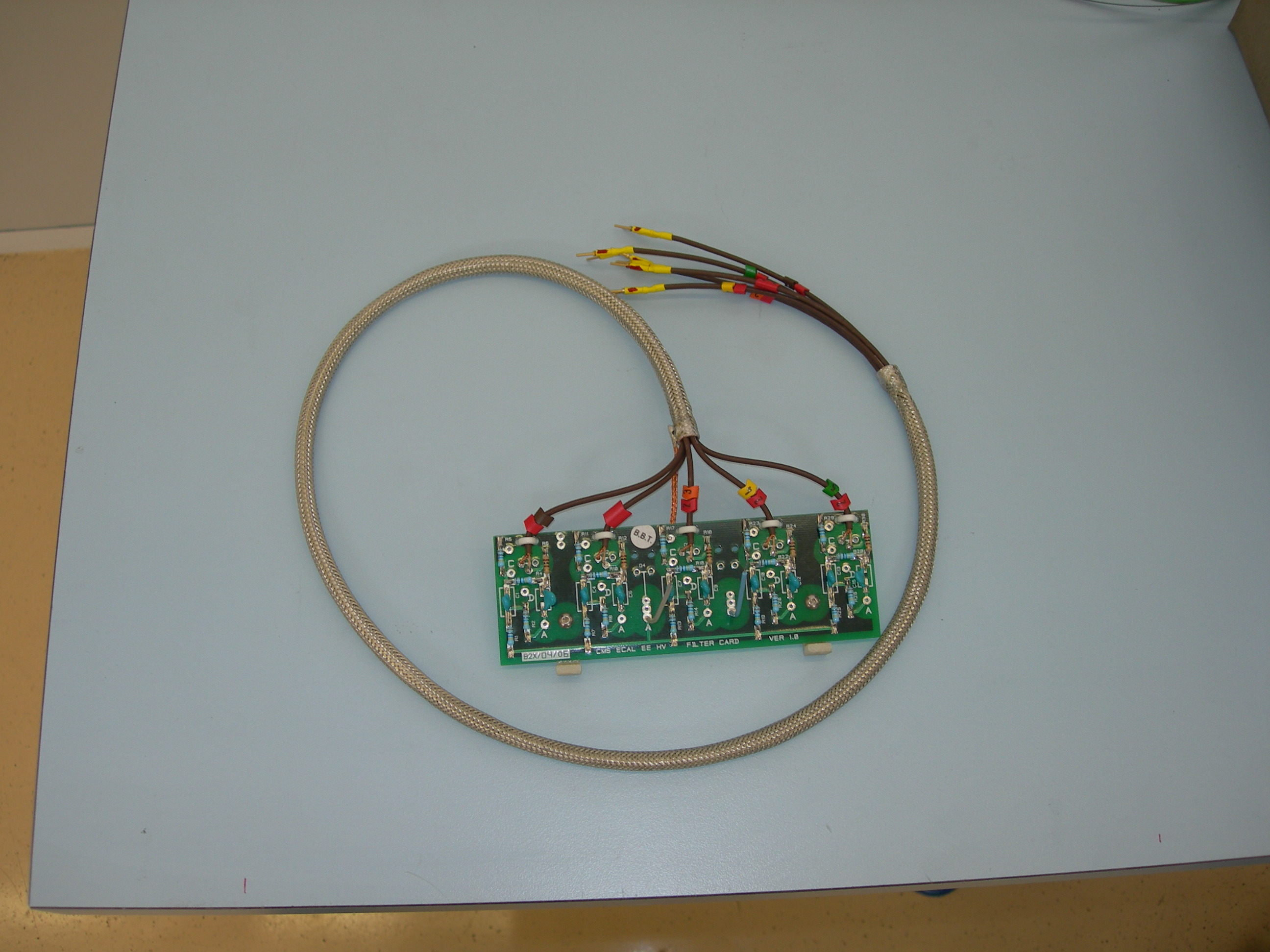
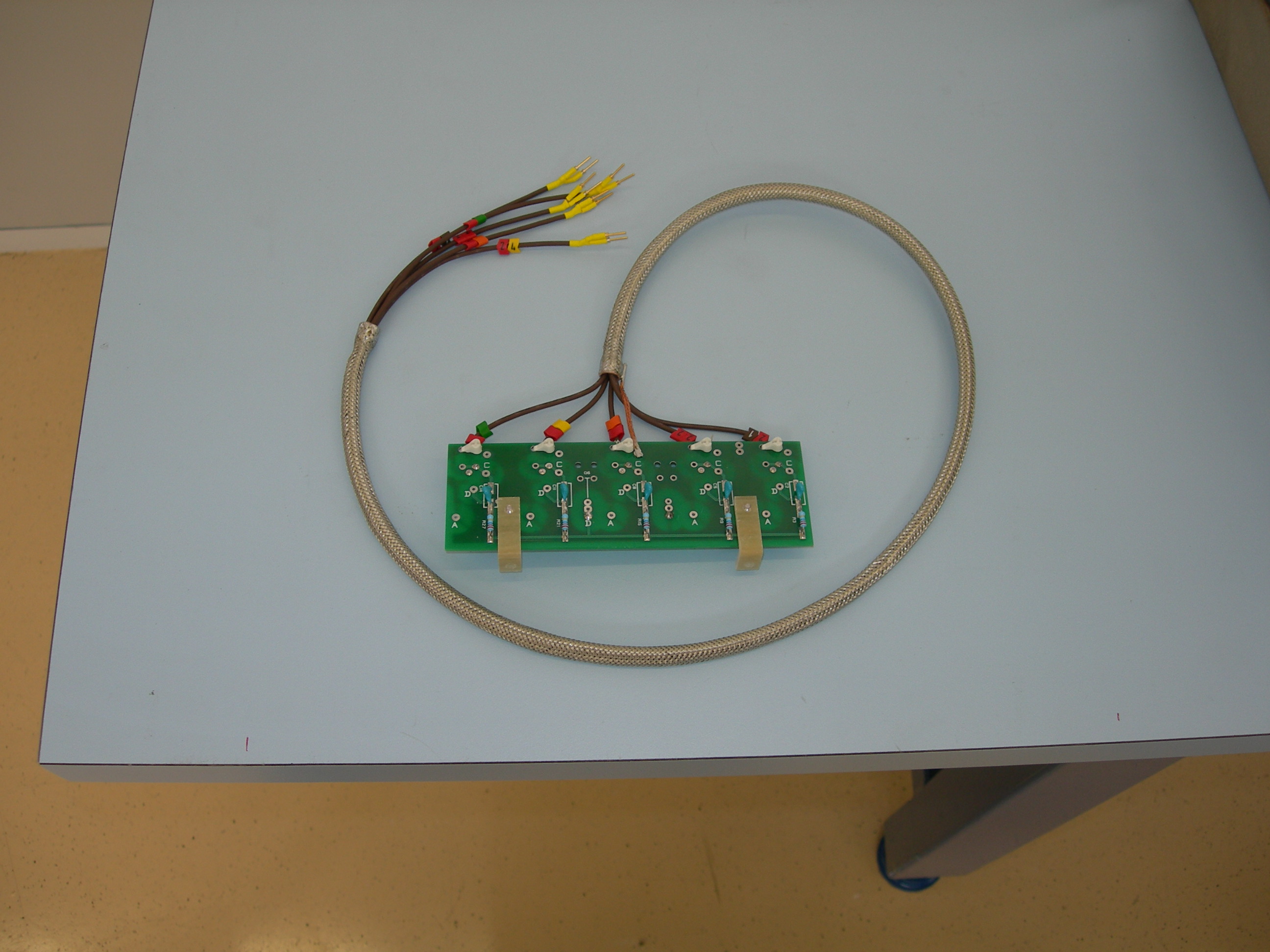
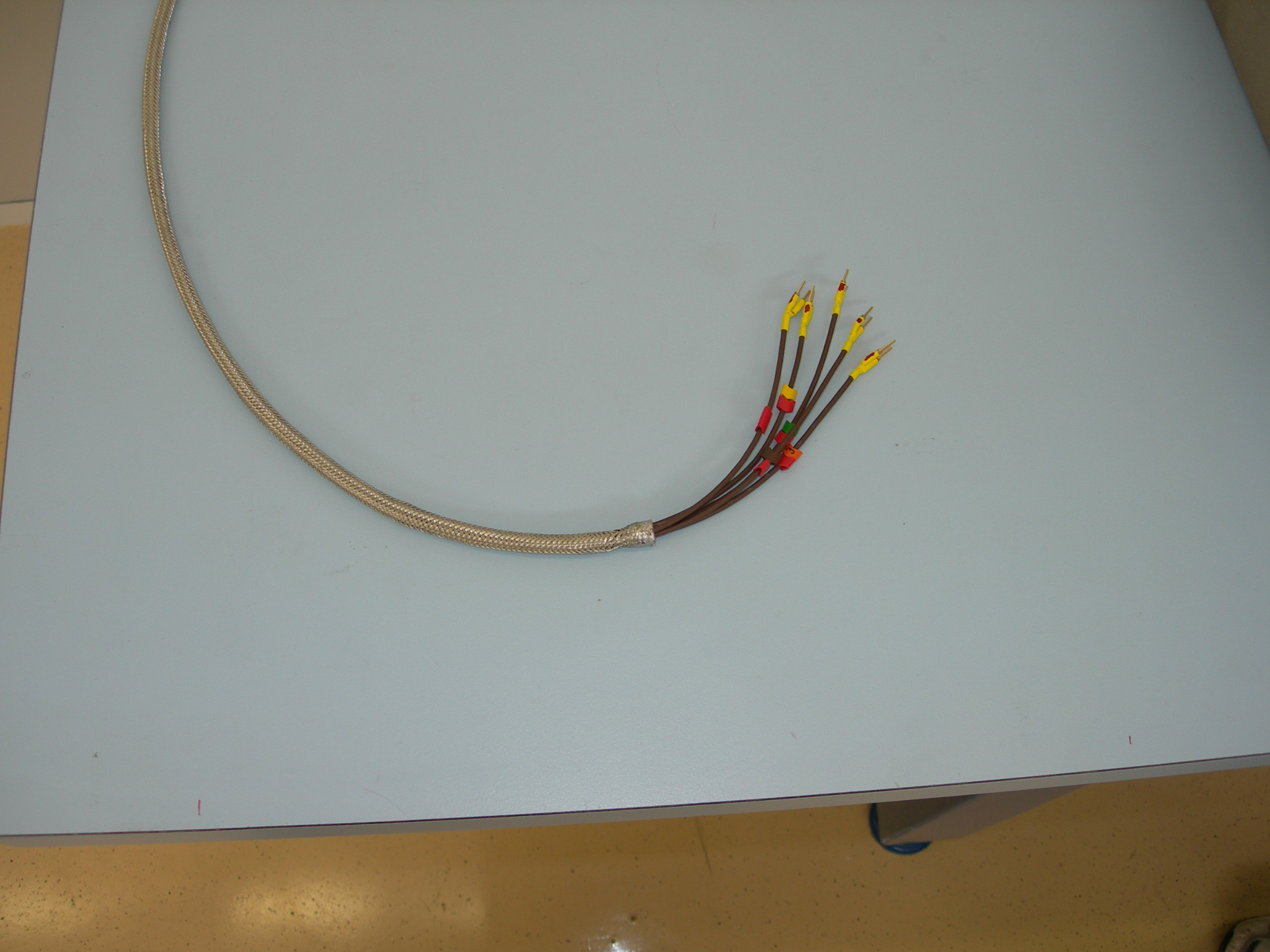
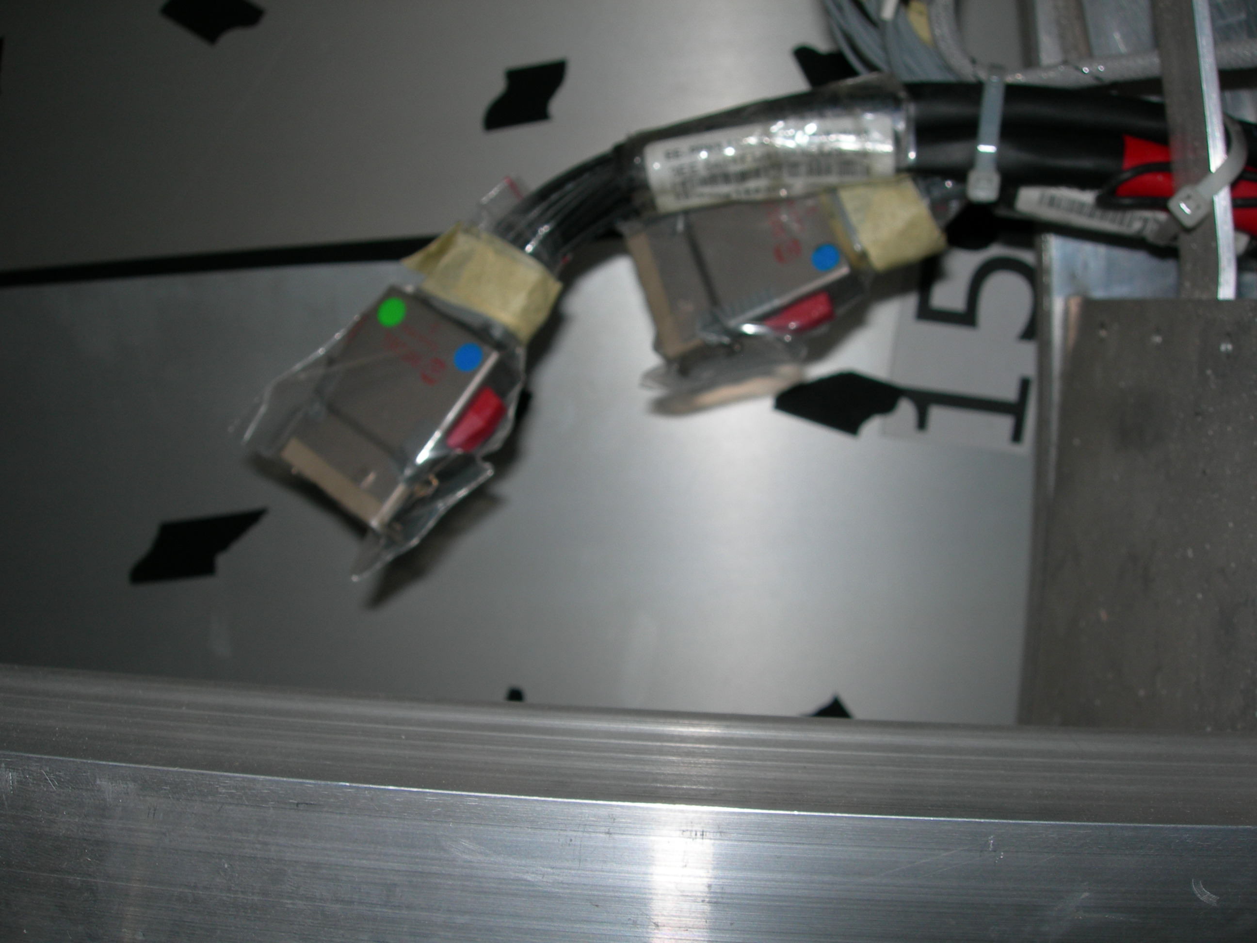
Photos, and dwg, of connectors at point 5, coming over HE and serving the EE patch panels, on HE- (HE minus), D Cockerill 18.1 ppt
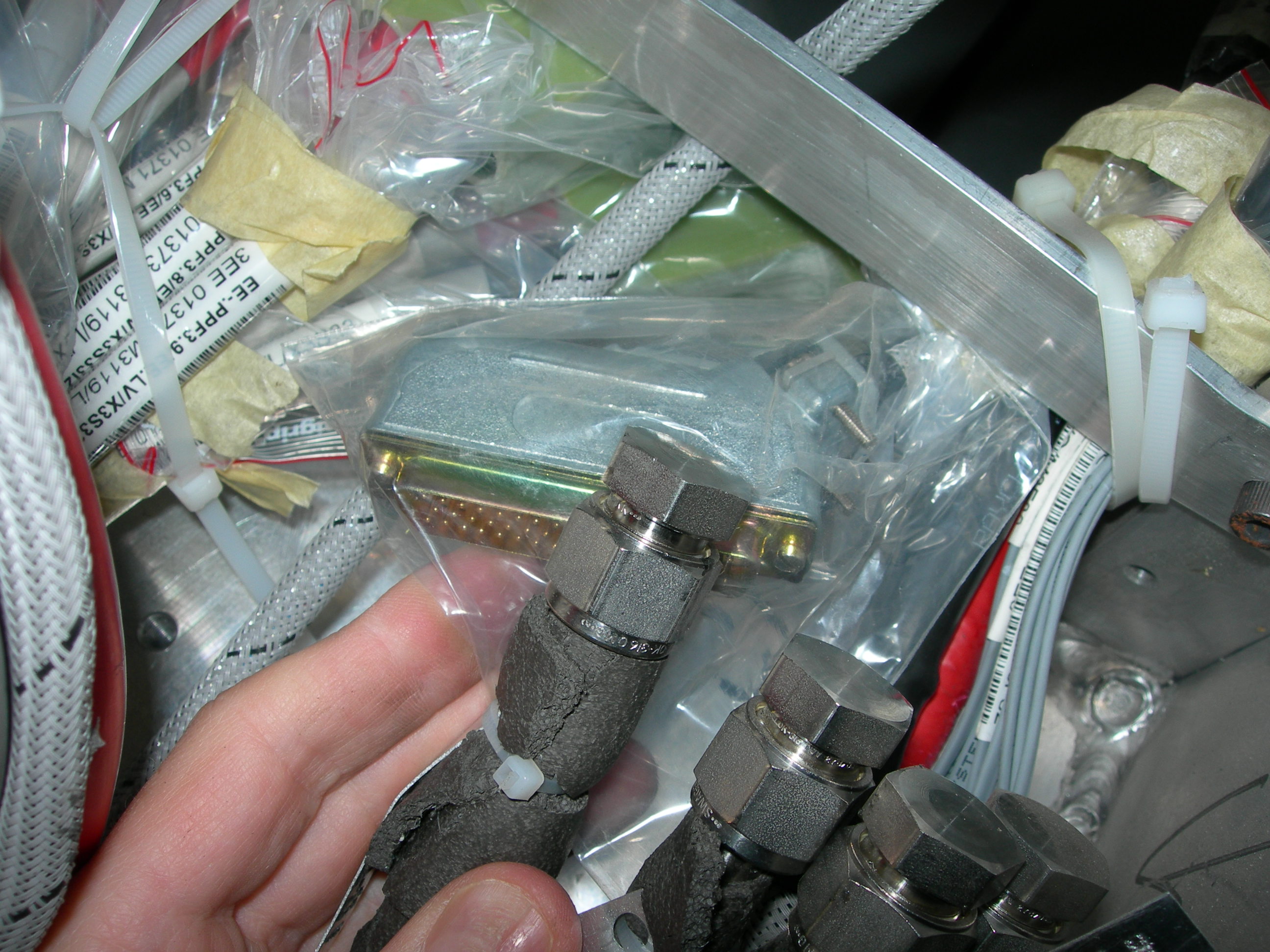
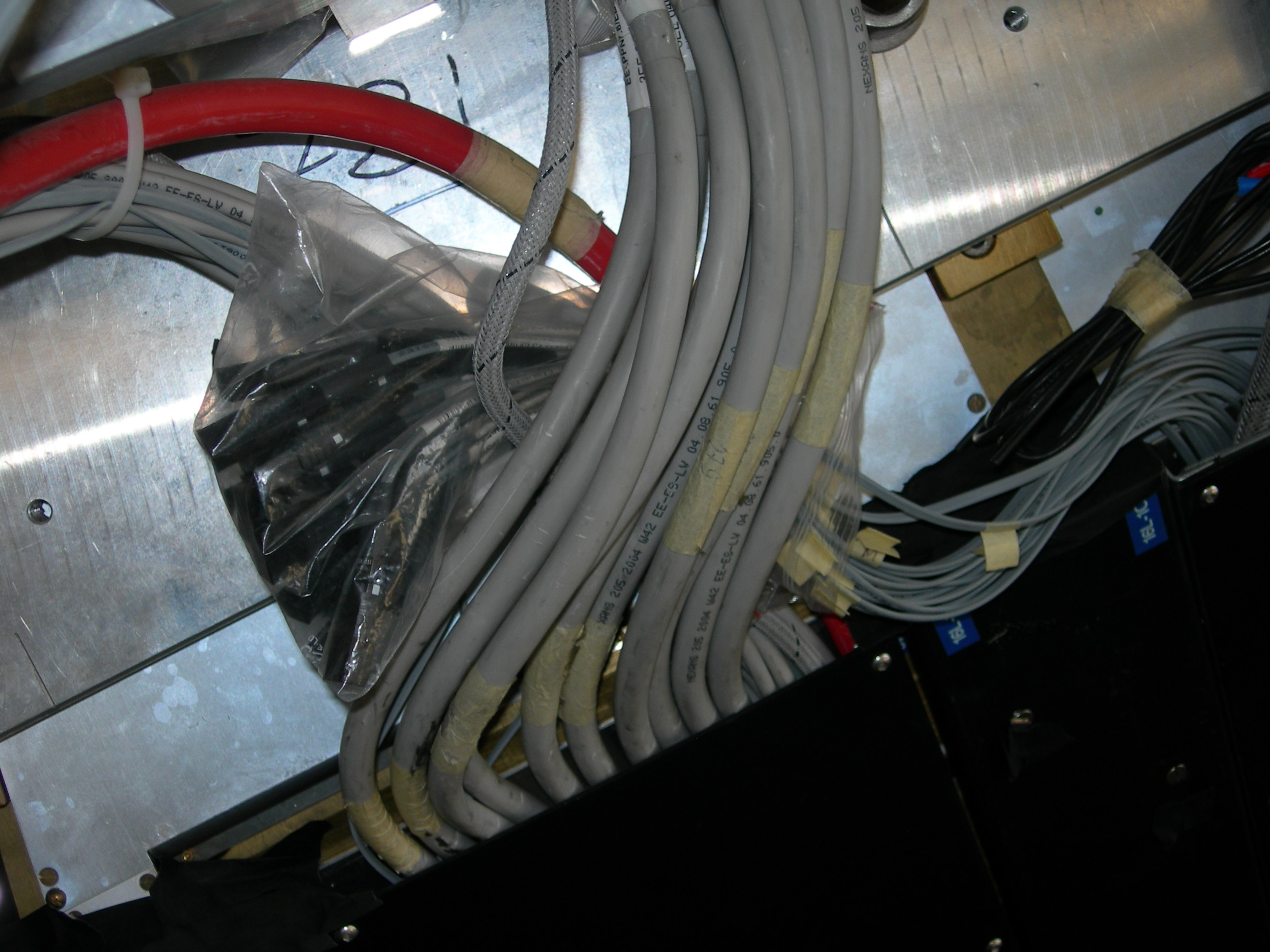
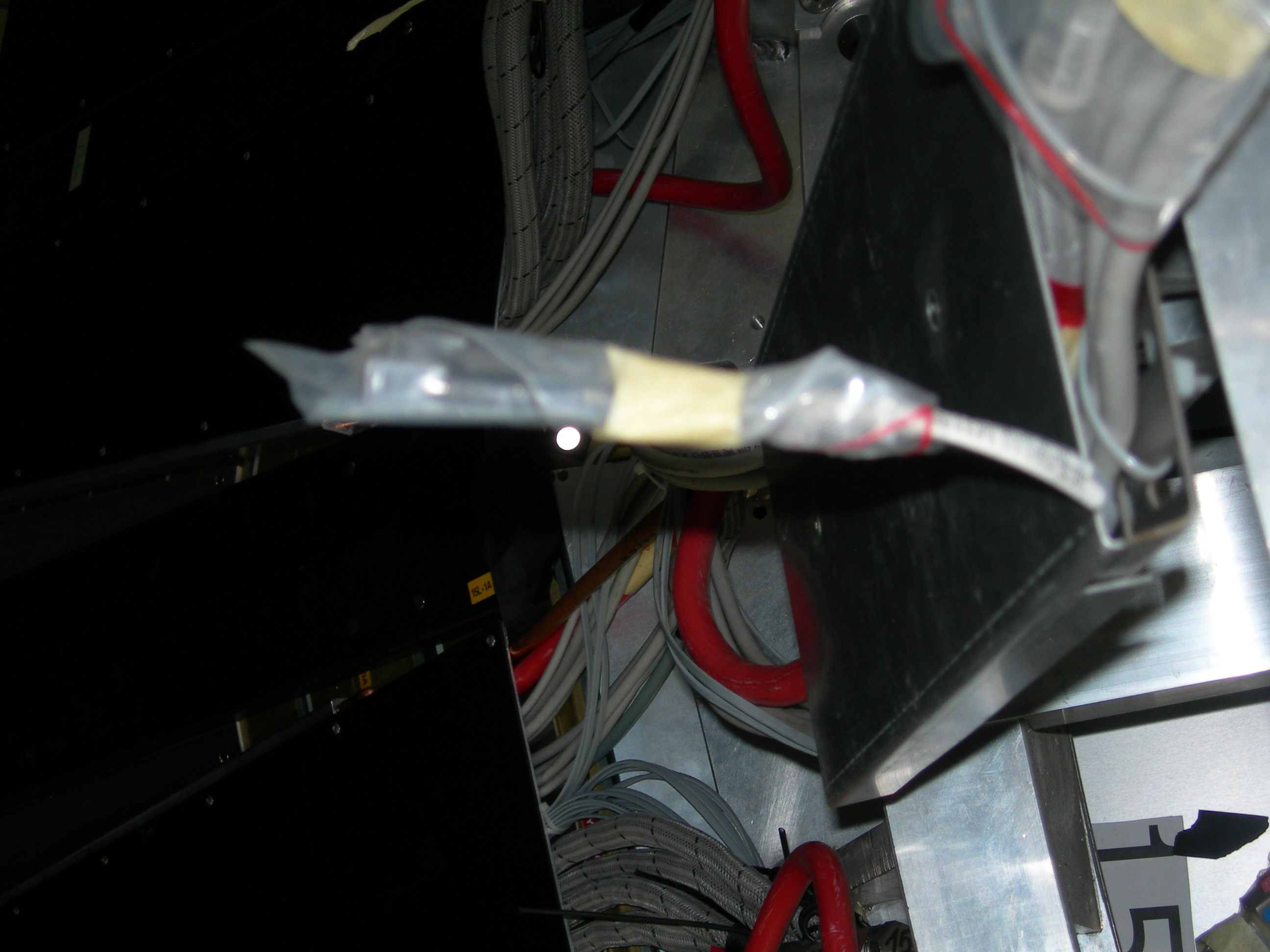
Photo, cables coming from HE
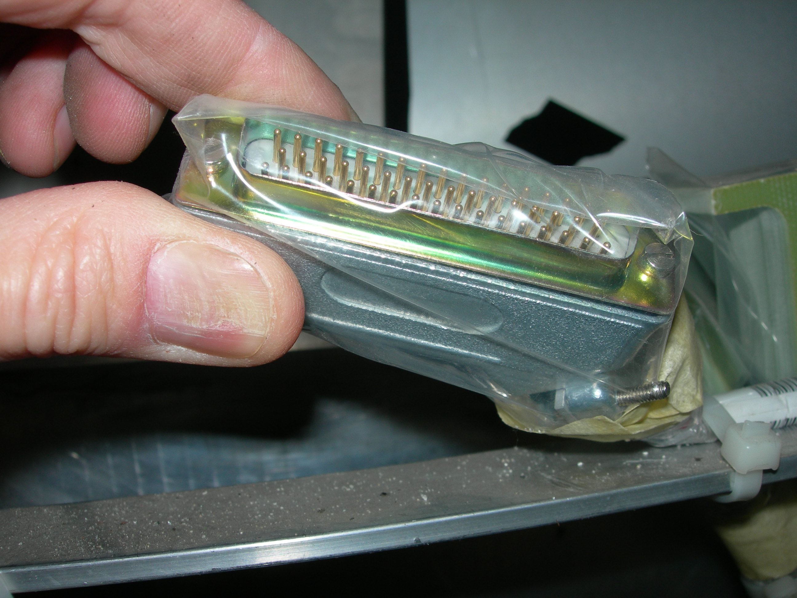
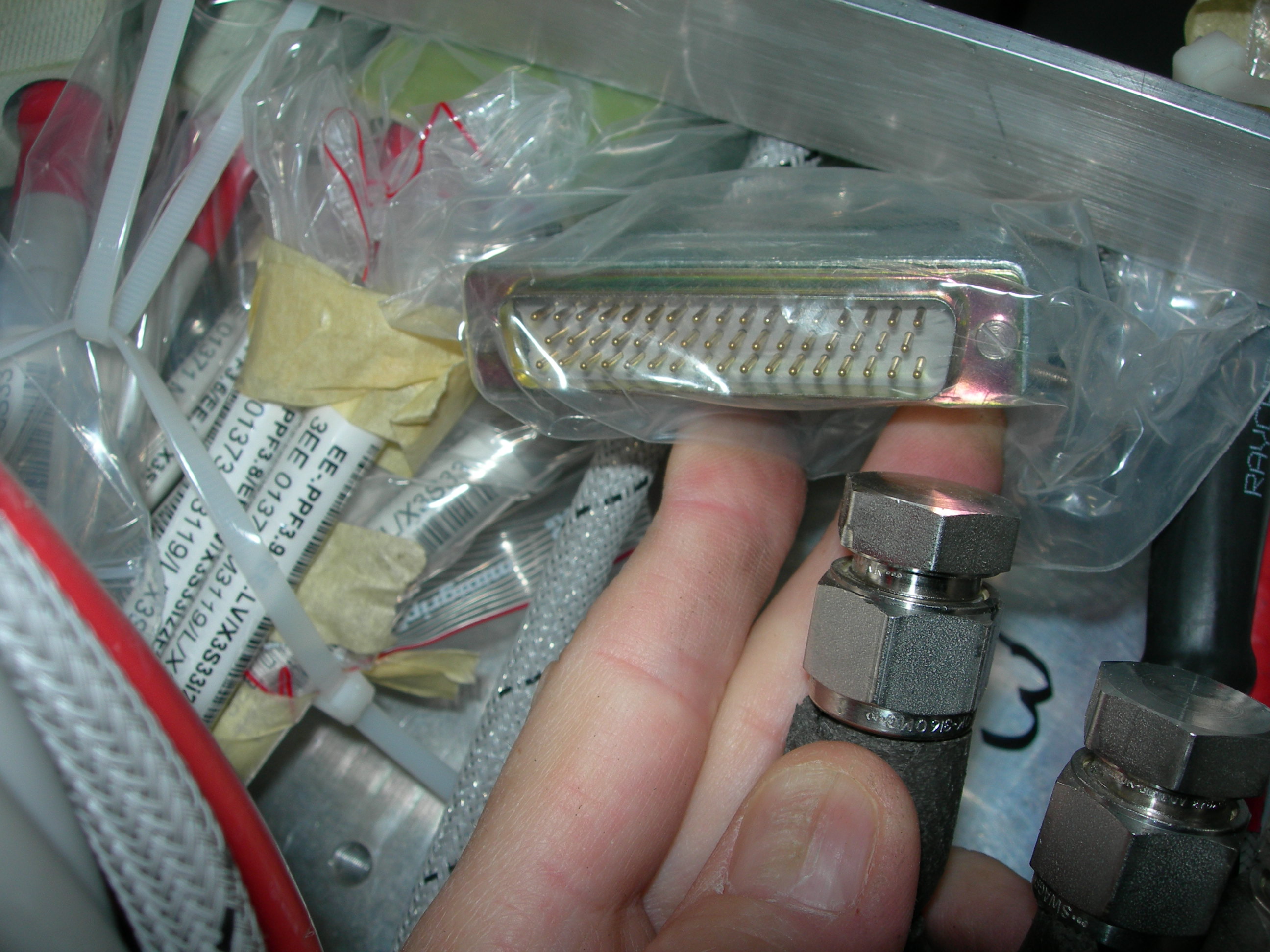
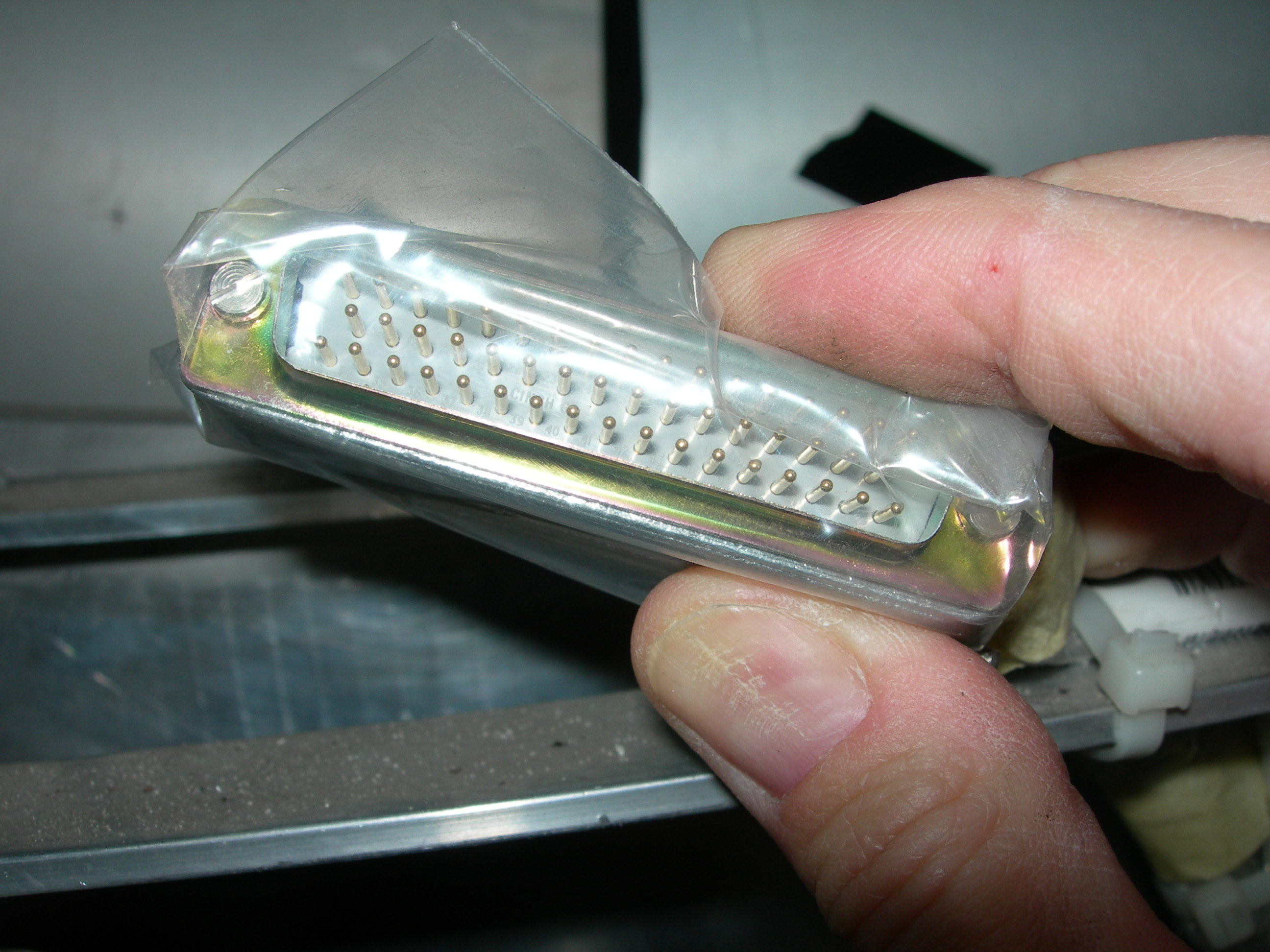
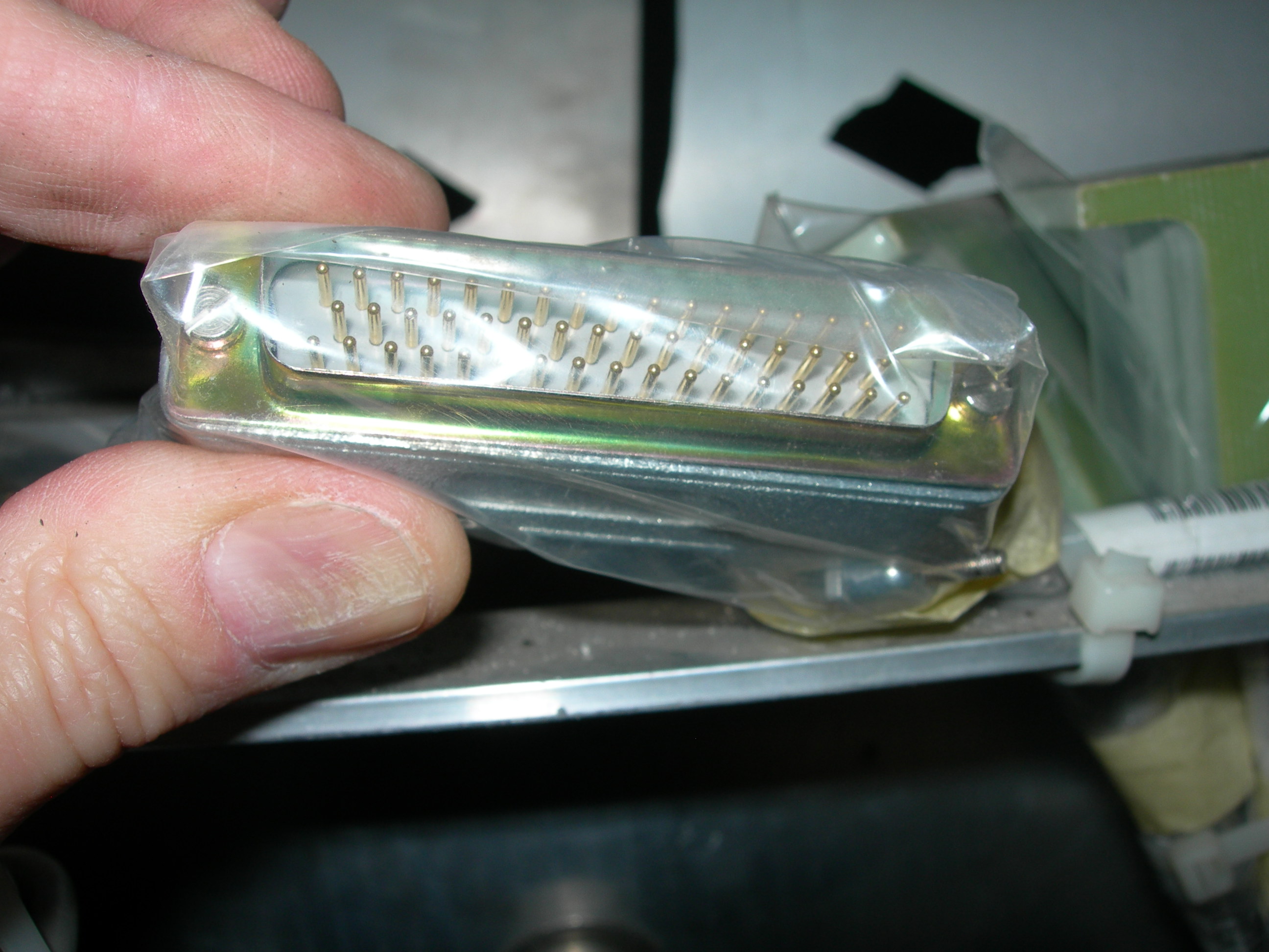
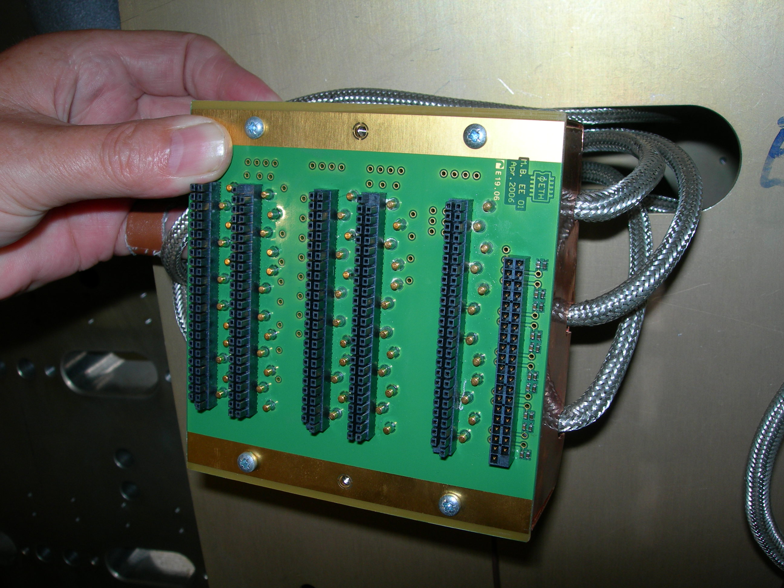
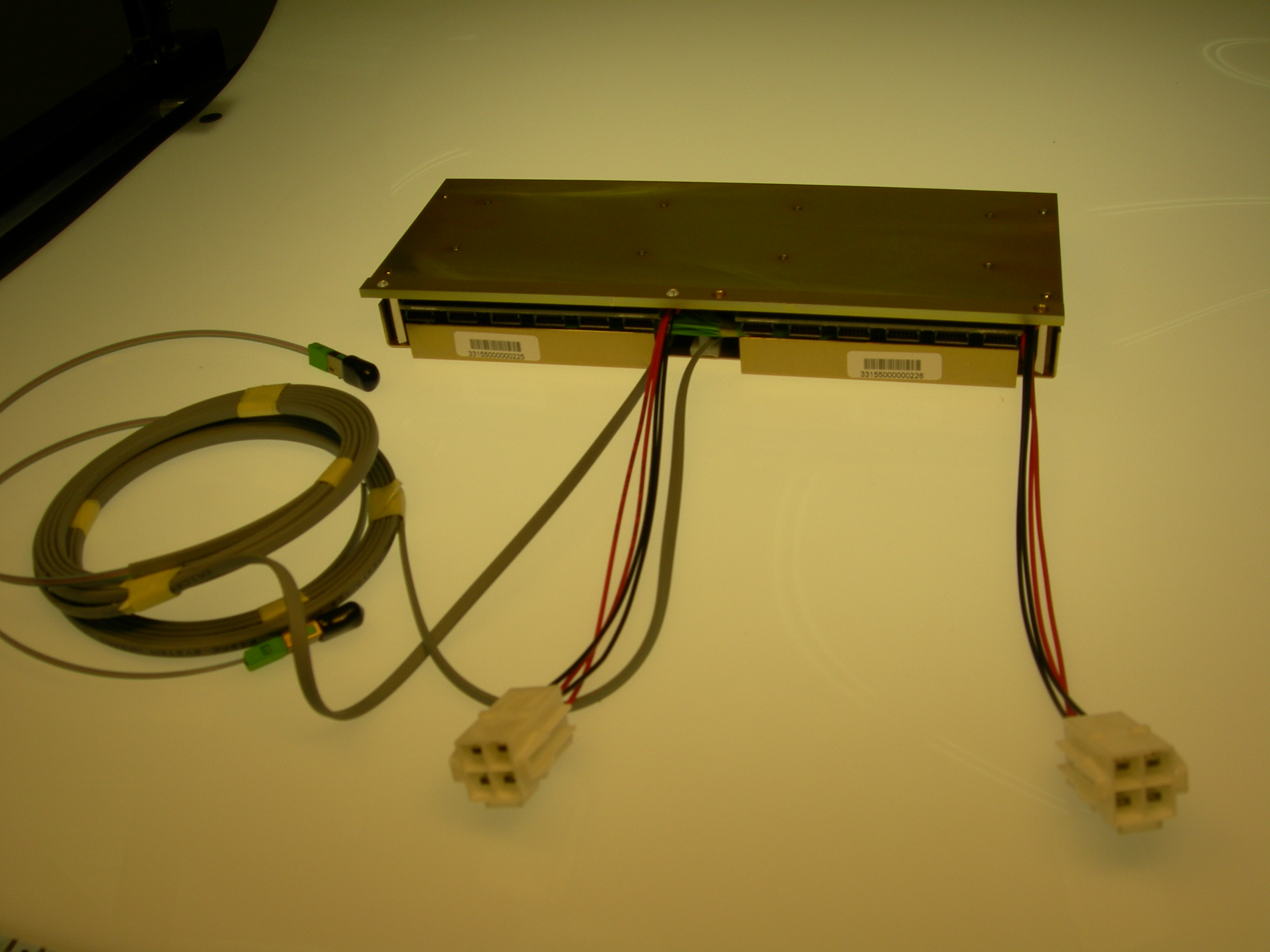
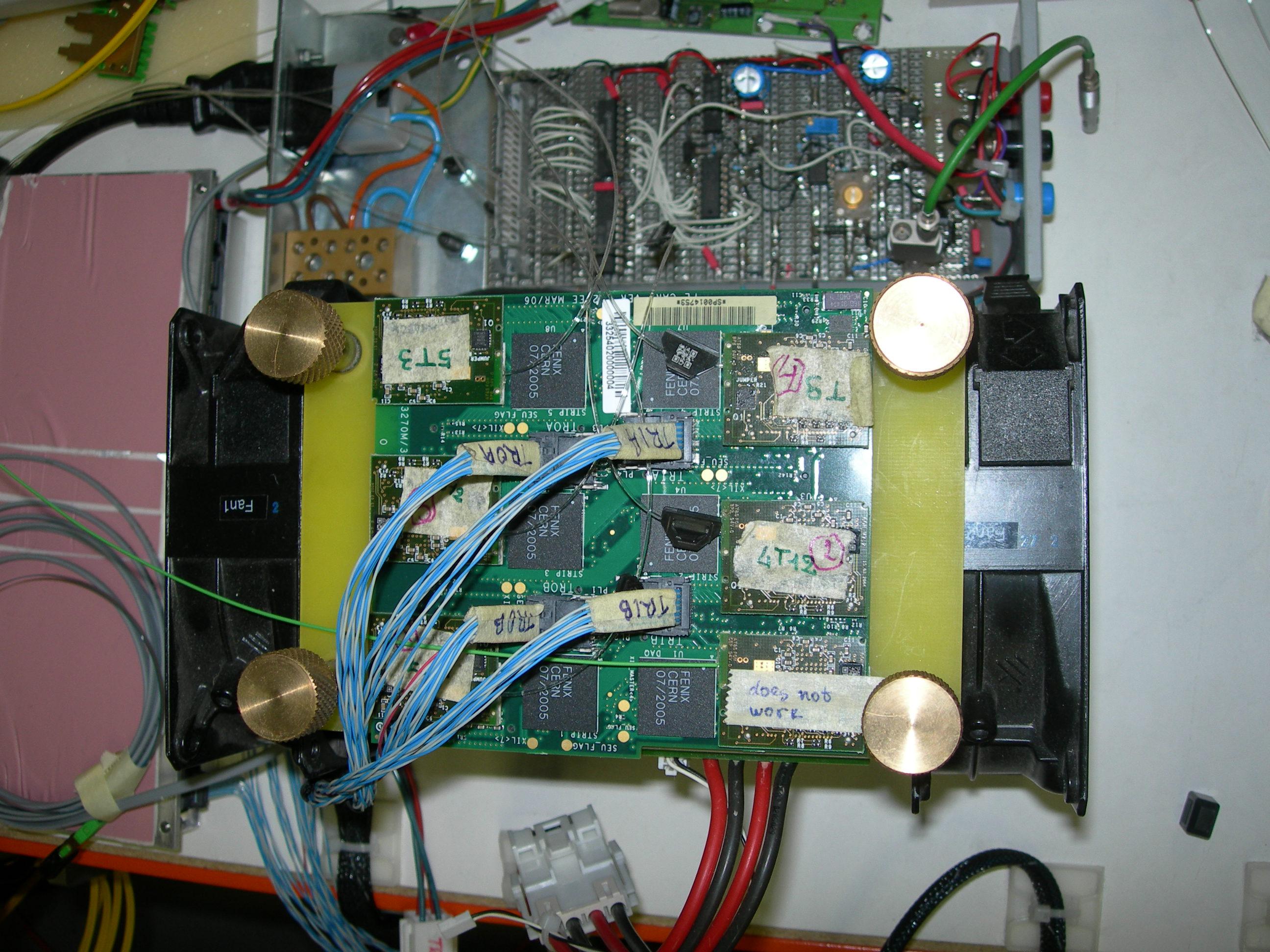
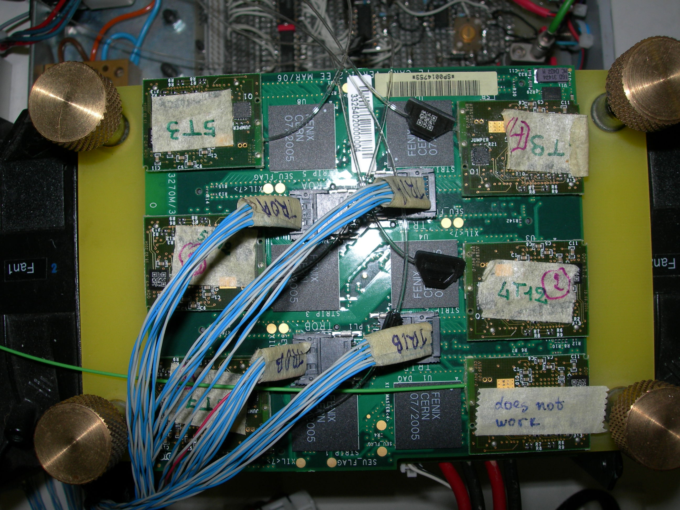
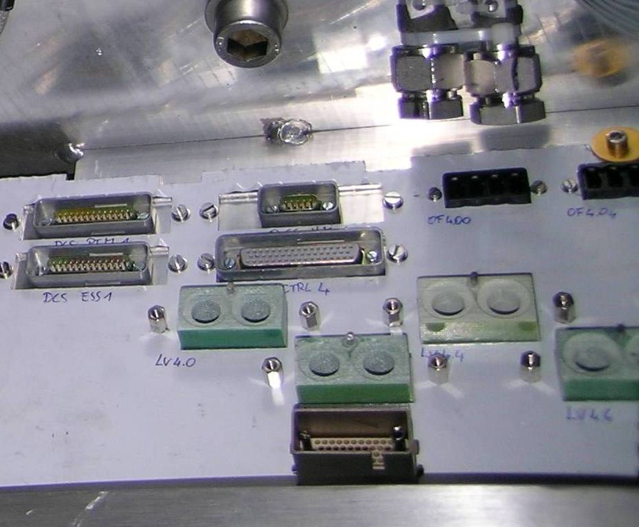
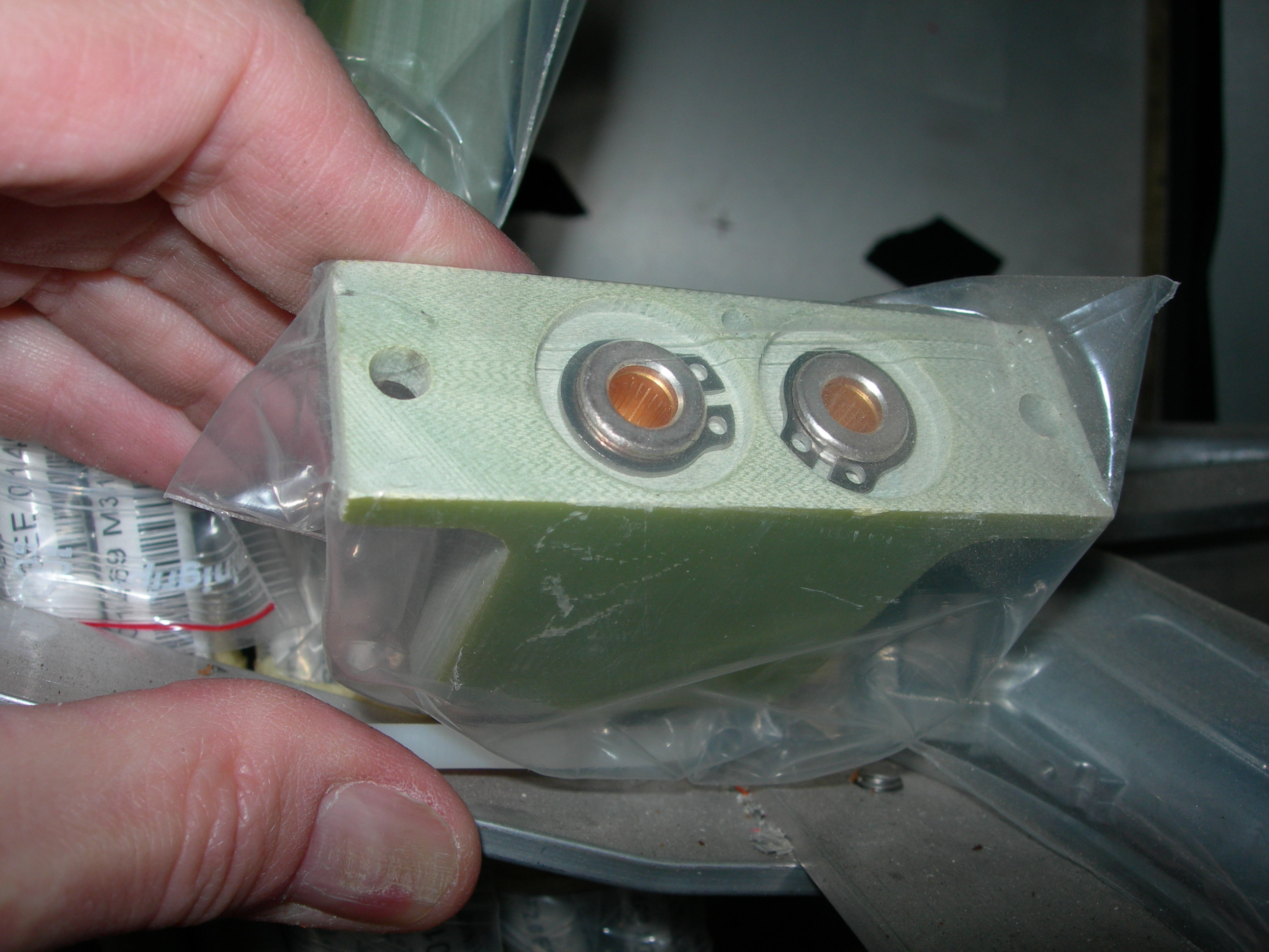
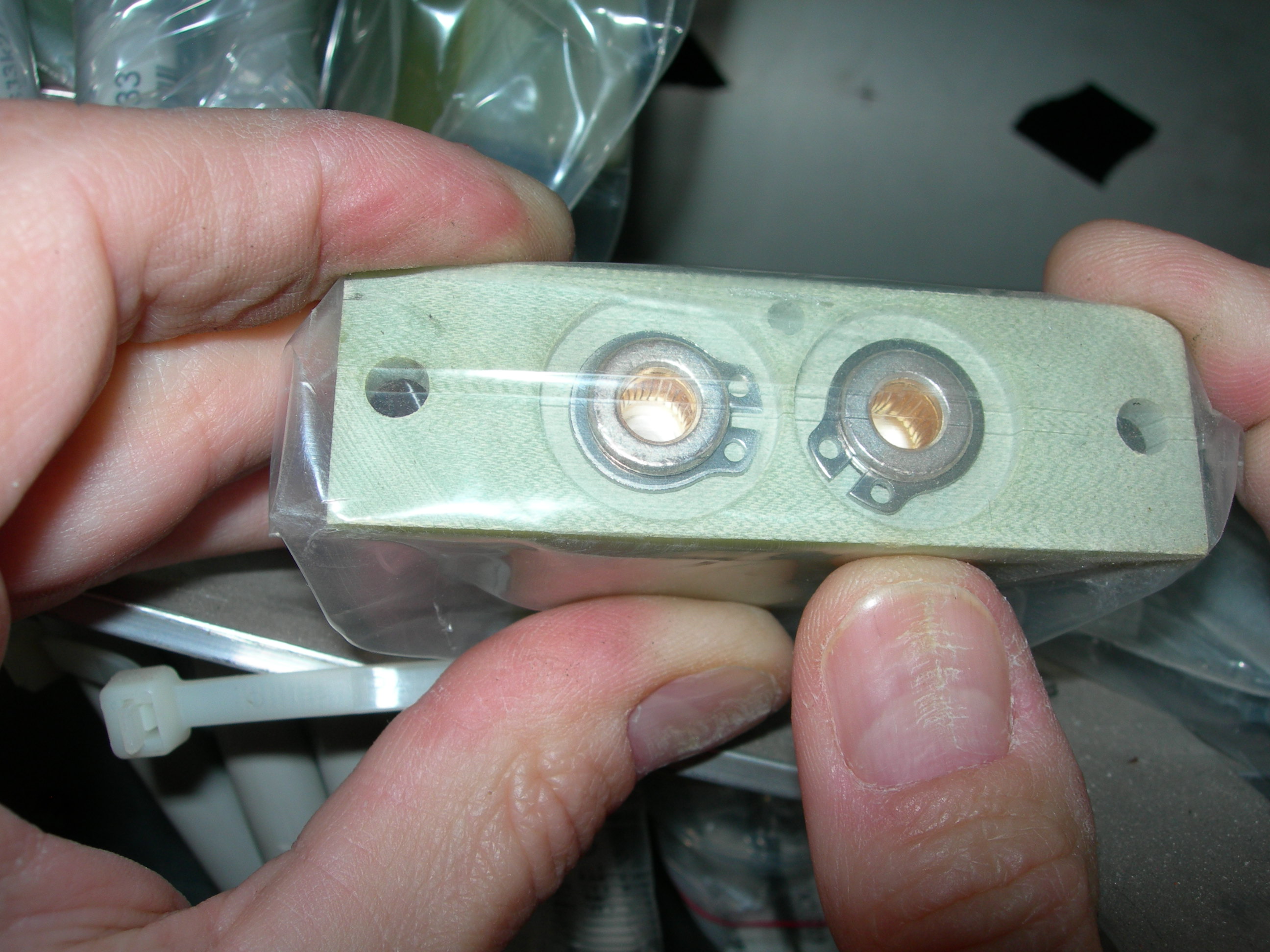
^ Comment: HV REDEL connectors. The nipple points towards the I.P. Pin 1 is on the top right hand corner, near the nipple, looking into the connector, with nipple on top. Pin 51 is on the bottom left hand corner looking into the connector, with nipple on top. Male fixing pin is near pin 1.
Female fixing pin is near pin 51. Consistent with photo 2005 below.
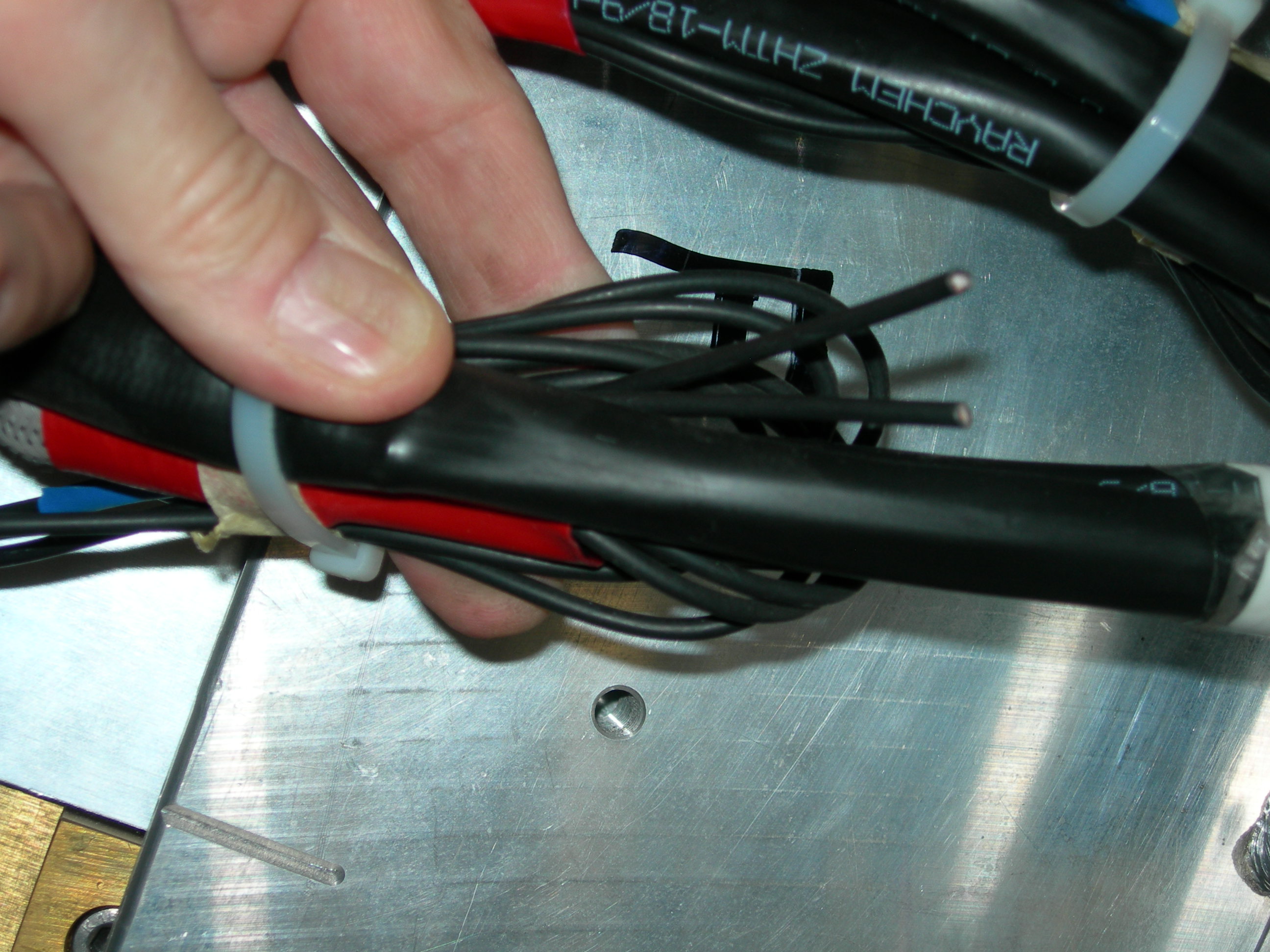
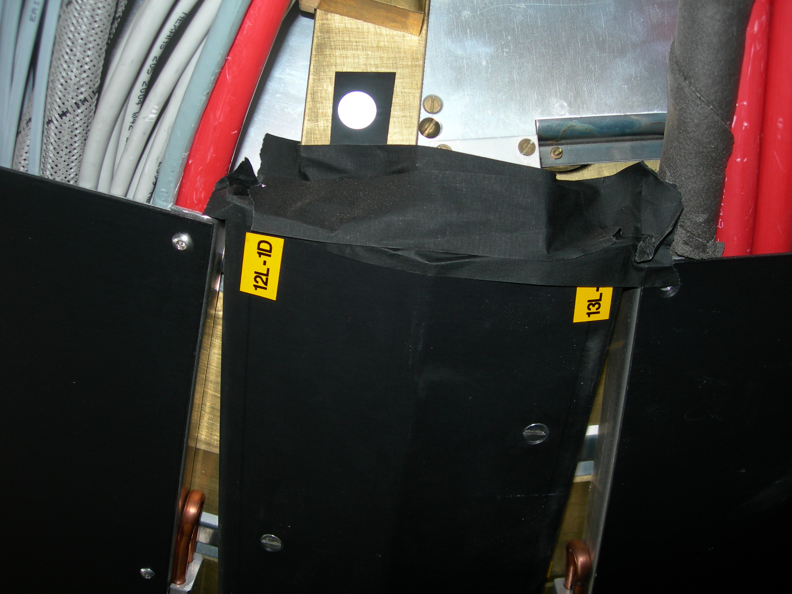
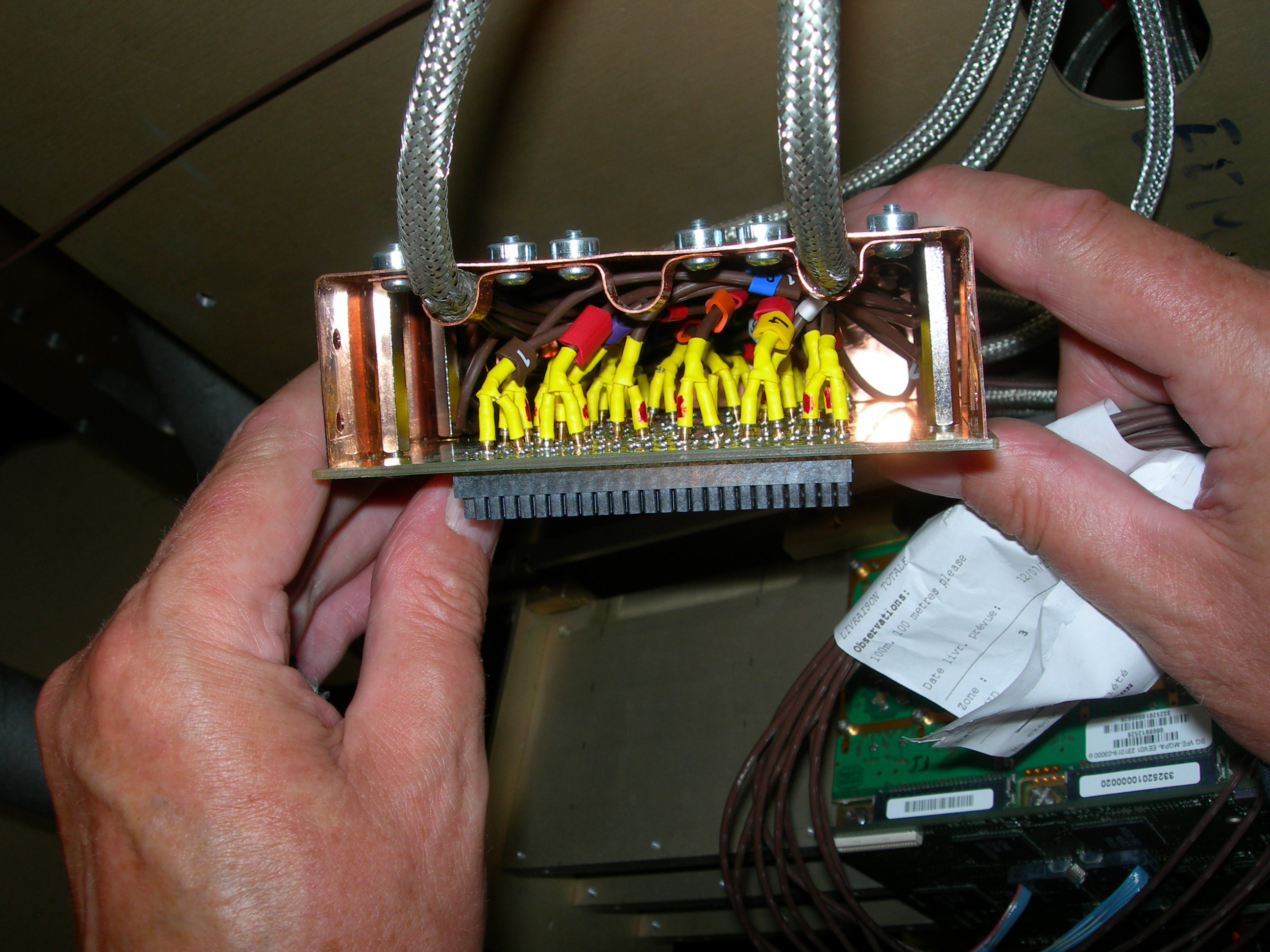
^ Comment: LV connectors. The locating hole is towards HE. Red is + (plus), Black is -ve (minus). Consistent with photo 2005 below.
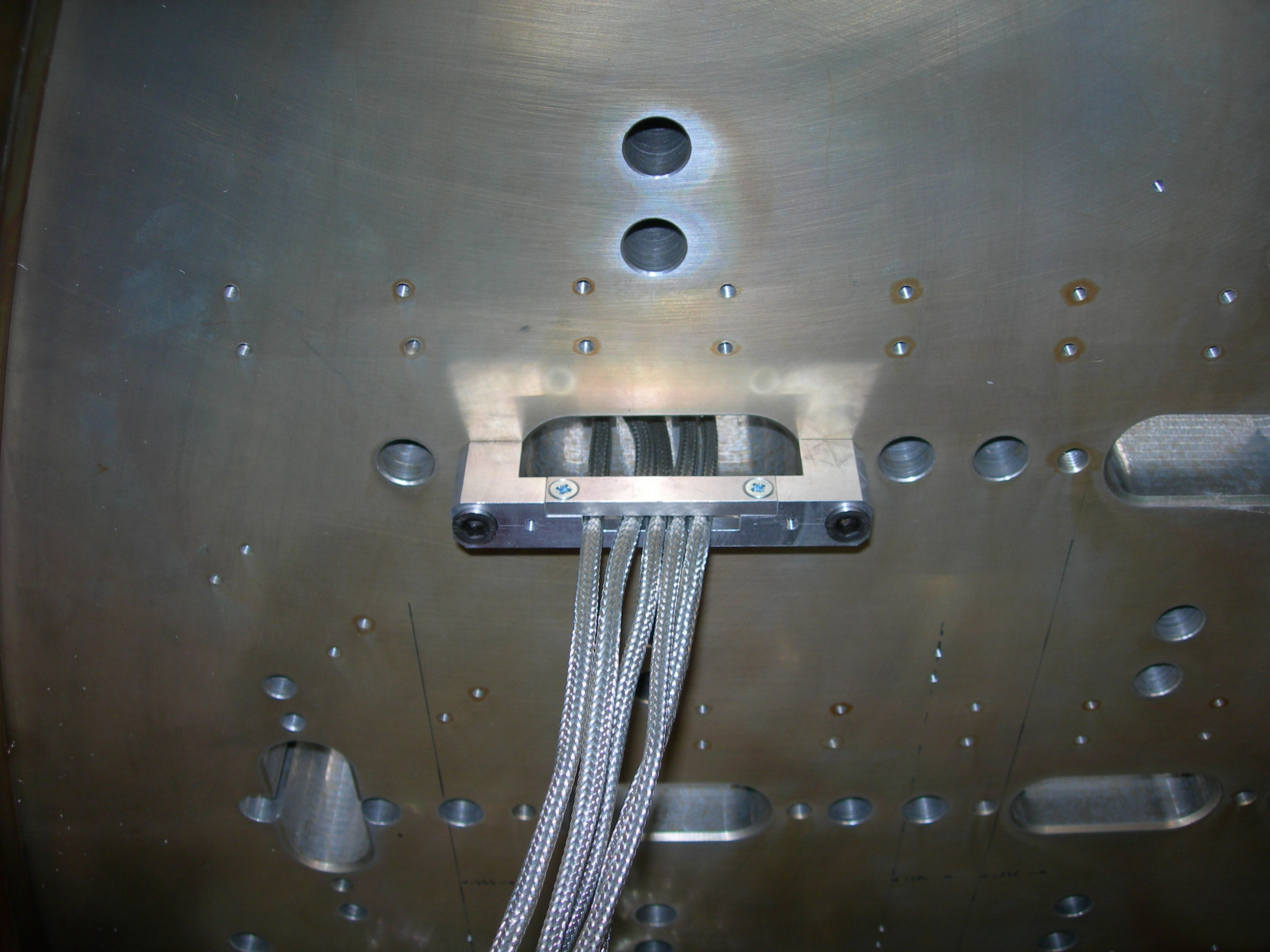
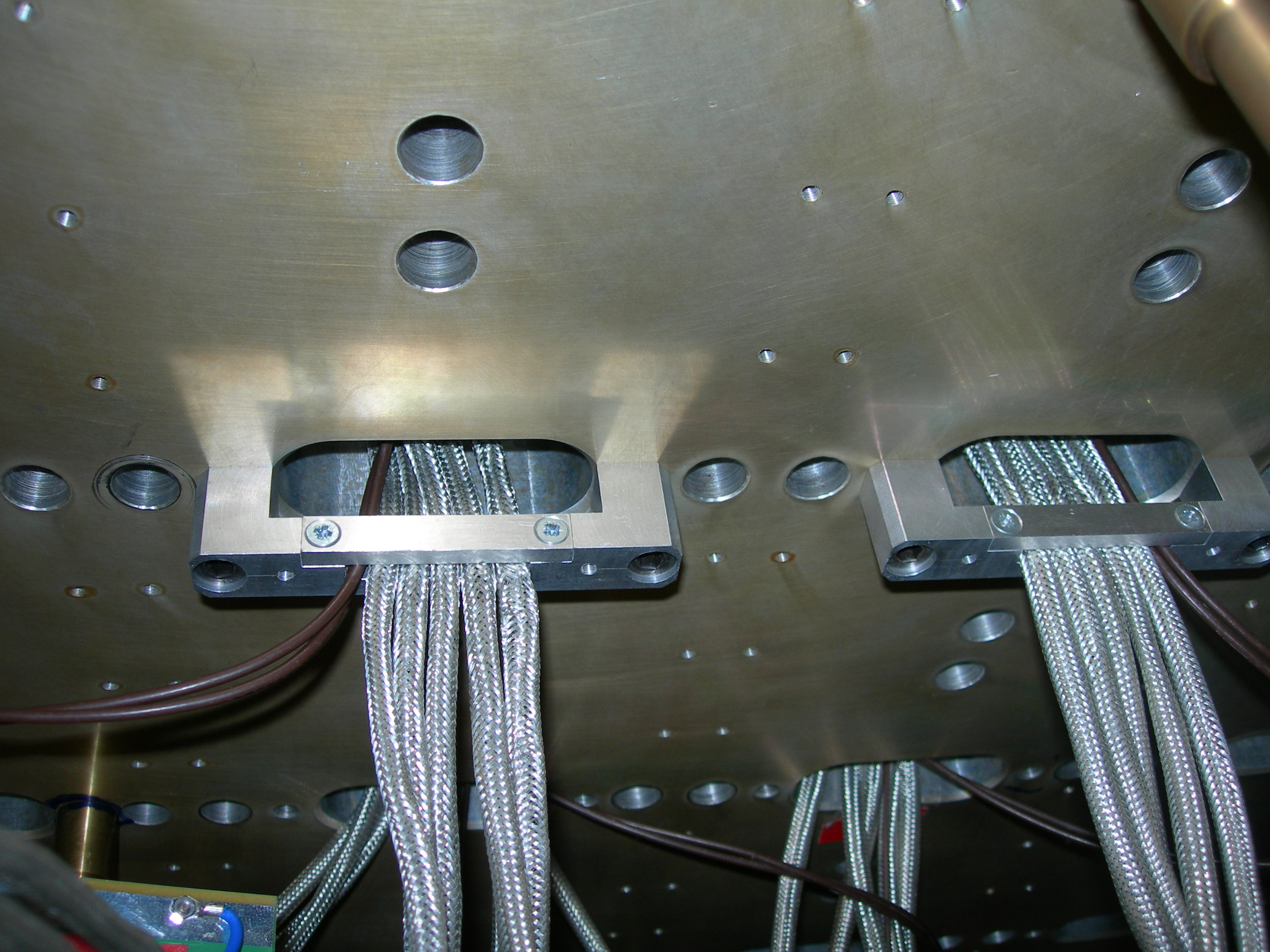
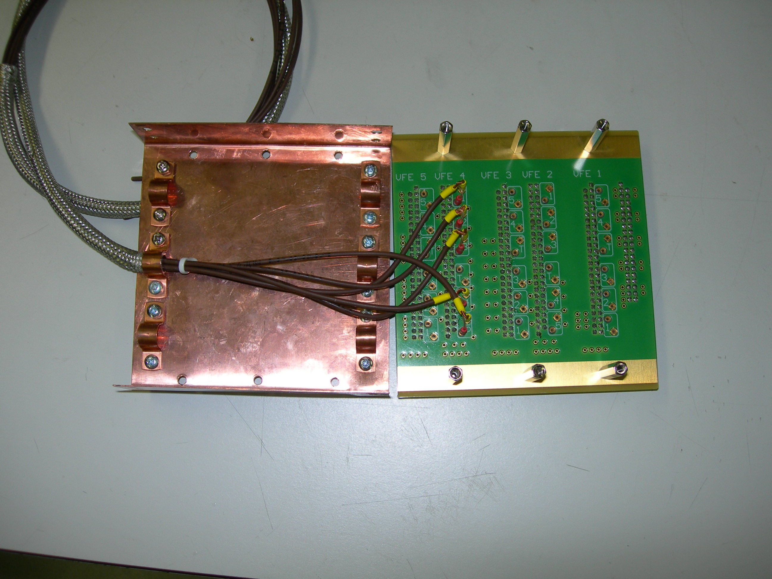
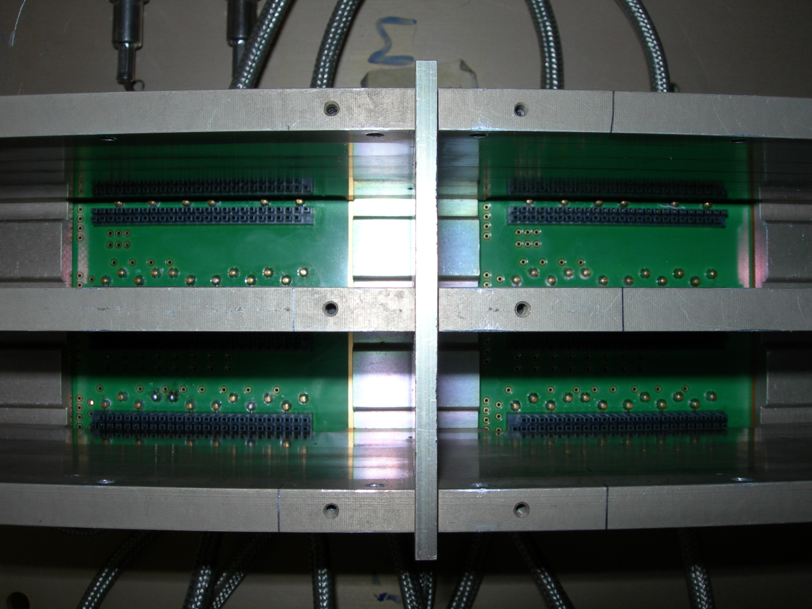
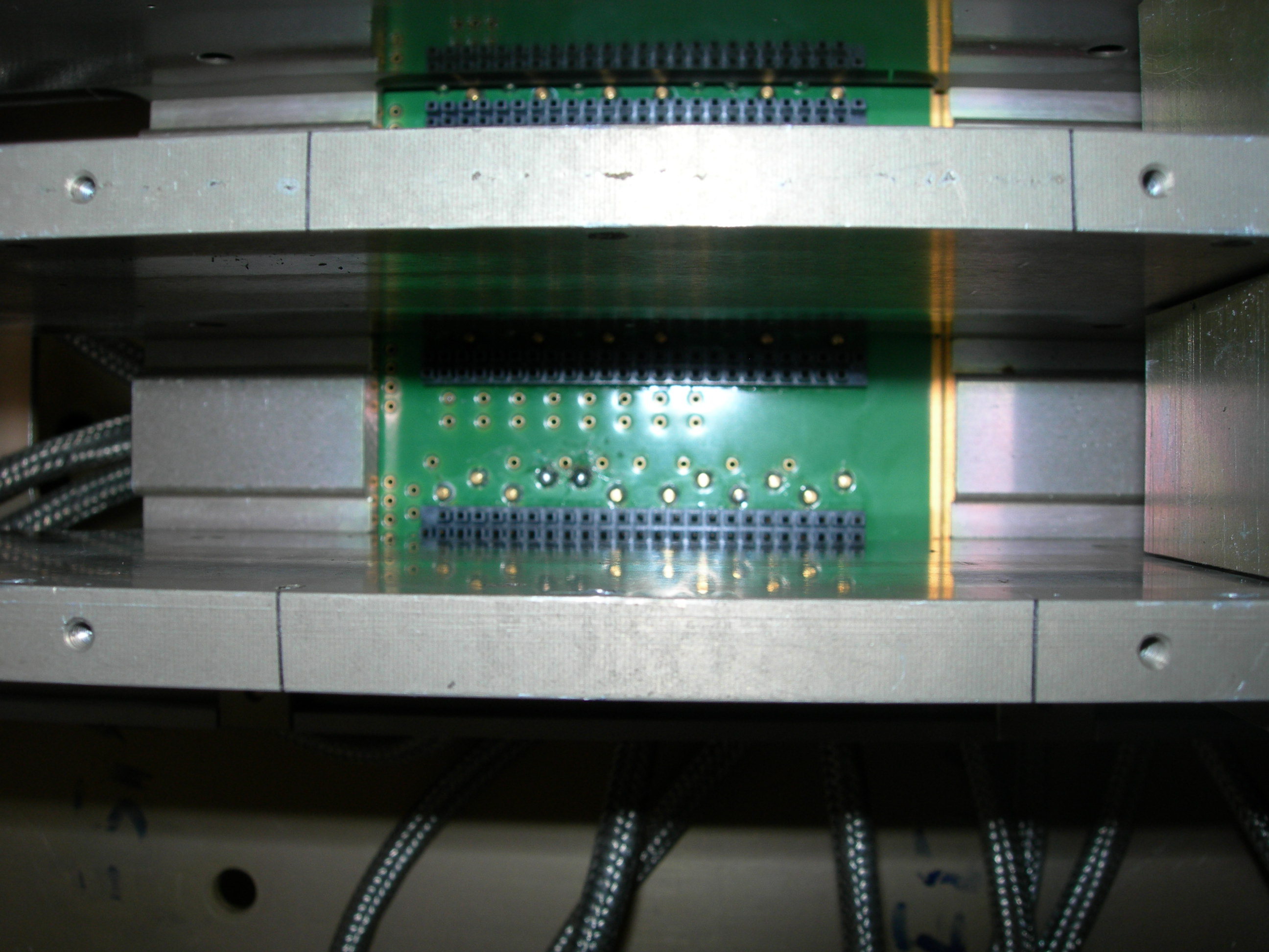
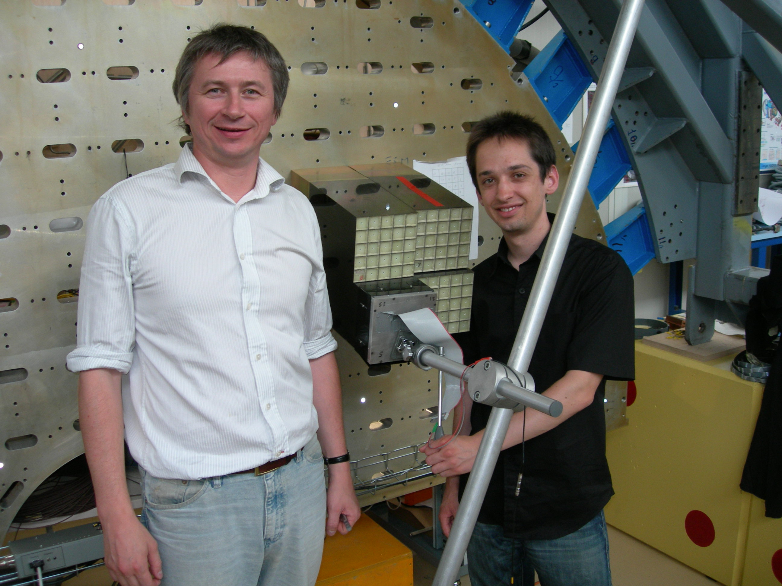
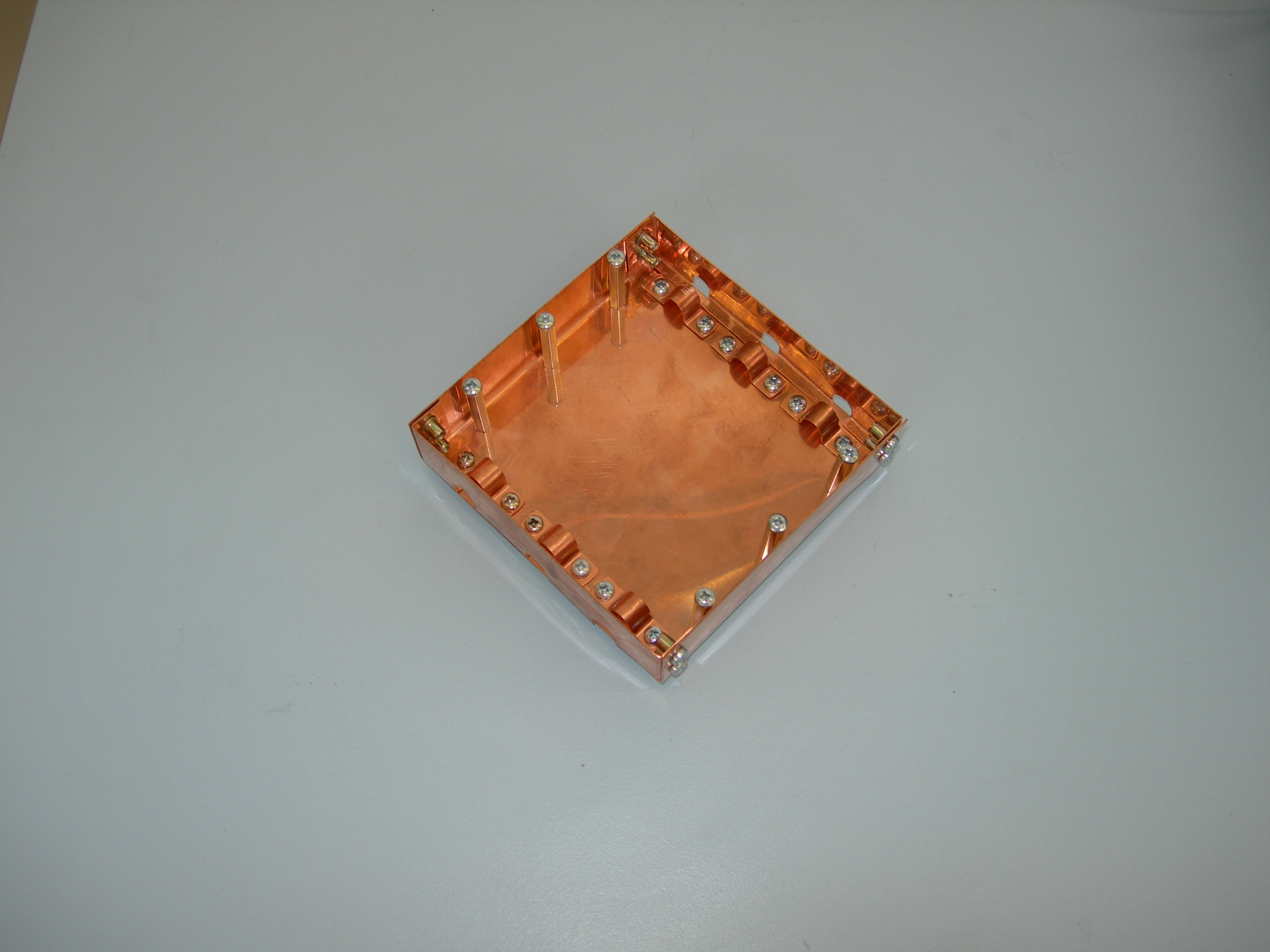
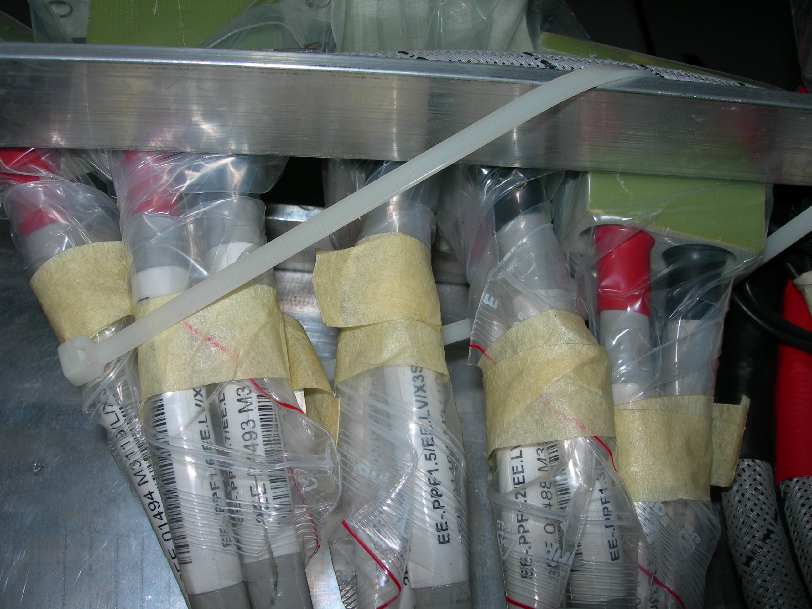
Other photos before installation of Dees, on 18.1